Geology Reference
In-Depth Information
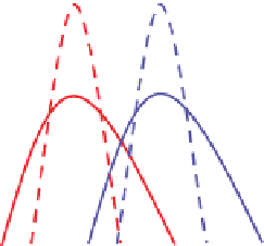
100
Solid line - wells
Dashed line - seismic
Seismic data
Well data
0
AI
Acoustic Impedance
Figure 9.21
Impedance distributions, well and seismic.
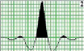
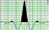
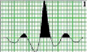
a)
b)
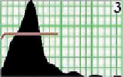
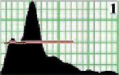
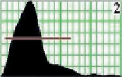
Figure 9.22
Wavelets and their spectra
for near, mid and far stacks (top to
bottom); (a) wavelets and (b) amplitude
and phase spectra (after Sirotenko,
2009
).
0.0250
0.5
50
0
-200
0
25
50
75
100
-50
-25 0 25 50
0.0250
0.5
50
0
-200
0
25
50
75
100
-50 -25 0 25 50
0.0250
0.5
50
0
-200
0
-50 -25 0 25 50
25
50
75
100
Time (ms)
Frequency (Hz)
9.2.7.1 Elastic inversion
-
the Connolly approach
The
Initially, separate inversions were performed on
near and far stack datasets and their results combined
(using projections,
Chapter 5
) to extract fluid and
lithology information (e.g. Simm et al.,
2002
). The
development of the extended elastic impedance con-
cept (
Chapter 5
) means that the fluid and lithology
projections can now be performed prior to inversion.
So, for example, pseudo-gamma ray inversions might
be generated from a reflectivity
method uses elastic impedance
(
Chapter 5
) as the basis of the starting model for
inversion. Single stacks (
Chapter 5
) can be inverted
using a background model generated with an imped-
ance calculated at the appropriate angle. Wavelets are
extracted from each stack so that separate inversions
are effectively scaled to the model generated at wells
(
Fig. 9.22
). This removes the need for any offset balan-
cing correction (
Chapter 6
) and effectively accounts for
any phase and frequency differences between stacks.
'
Connolly
'
projected to
an angle that correlates with gamma ray (
Chapter 5
)
(e.g. Neves et al.,
2004
). A subsequent development in
'
stack
'
210