Geology Reference
In-Depth Information
-200
-150
1
50m
-100
0.1
-50
0.01
0
0.001
0.0001
50
100
150
200
Hz
Bandpass 11,20,56,64Hz
~3.5 octaves
Amplitude
-200
-150
1
-100
0.1
-50
0.01
0.001
0
0.0001
50
100
150
200
Hz
Bandpass 5,11,56,64Hz
~4.5 octaves
Amplitude
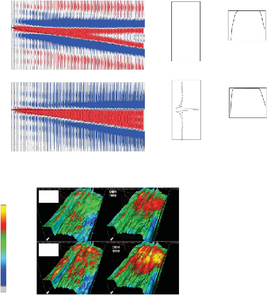
Figure 9.13
Bandlimited impedance wedge models using wavelets of different bandwidth; (top) 11
20
56
64 Hz bandpass filter
-
-
-
(simulating surface seismic), (bottom) 5
11
56
64 Hz bandpass filter (simulating ocean-bottom hydrophone).
-
-
-
Figure 9.14
Comparison of inversion
results from surface streamer and ocean
bottom hydrophone; impedance near
top reservoir, after Wagner et al.,
2006
.
Streamer
1995
OBH
1995
AI (m/s.g/cc)
Low
5700
Streamer
1998
OBH
1998
High
7300
Undefined
overburden. In principle it is possible to use a laterally
varying wavelet in the inversion, but in practice it will
be hard to define the exact nature of the lateral vari-
ation between well control points.
effect using a simple wedge model with an artificial
well providing impedance control. When only the top
surface of the wedge is used (
Fig. 9.18a
) the tuning
effects are not fully removed from the data. Inputting
the base of the wedge into the model as well as the top
(
Fig. 9.18b
) gives a good representation of the imped-
ance in the wedge. The interpreter may be wary of
inputting top and base horizons to the inversion,
however, if the objective is to find a pinch out trap
9.2.4.4 Horizon constraints and tuning
In model-based inversions the choice of guiding hori-
zons used in the starting model can have a significant
impact on the final result.
Figure 9.18
illustrates this
206