Geology Reference
In-Depth Information
Inverted
relative
impedance
AI
Rc
Synthetic trace
Inverted Rc
Inverted AI
- +
- +
- +
0
0.1
0.2
0.3
0.4
0.5
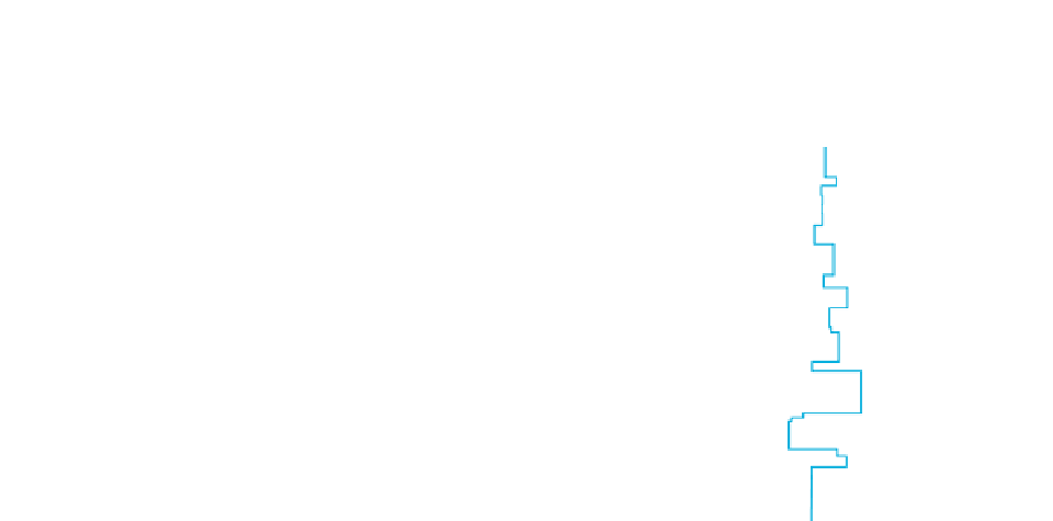
Figure 9.3
Model data example illustrating sparse spike trace inversion (based on data from Oldenburg
et al.
,
1983
). Note how the inverted
AI
trace is a blocky simplification of the well impedance.
the seismic data, and creates impedance changes only
when they are required to match the seismic response.
Although the seismic is justified in the solution, the
result need not be consistent with what is known
about the geology from well data or other observa-
tions. Thus the inversion result may be an over-
simplified version of the subsurface. Other methods
of trace inversion provide for the incorporation of
geological information with varying levels of sophis-
tication, as will be discussed.
In practice it might be better to use the seismic
interval velocities as a way to extrapolate log-based
impedances away from the wells by using a cokriging
approach.
The final inversion result is a solution in which the
impedance model has been checked against the seis-
mic traces and the errors calculated and minimised. If
the wavelet is adequately described then the problem
of tuning can be partly addressed. Various algorithms
have been employed in the inversion process, e.g.
Generalised Linear Inversion (GLI) (Cooke and
Schneider,
1983
) and the Seismic Lithologic method
SLIM (Gelfand and Larner,
1983
). Depending on the
complexity of the algorithm and the compute power
available, the inversion of a complete seismic cube
may take hours, or perhaps days, to run.
Model-based inversions typically employ con-
straints to prevent the impedances in the solution
wandering so far from the initial model that they are
geologically impossible. These may be either hard
boundaries that the solution is not allowed to cross,
or soft constraints in whose vicinity a penalty is added
to the synthetic error (the measure of the difference
between the modelled and real seismic traces) that is
being minimised. In the first case limits could be set
as a maximum fractional change in the impedance
from the starting model values. If the solution found
closely adheres to this hard boundary over large TWT
ranges, it is an indication that the starting model is
9.2.3 Model-based inversion
Perhaps the most popular broadband inversion tech-
nique for which there is readily available commercial
software is called model-based inversion (e.g. Russell
and Hampson,
1991
). Model-based inversions use an
iterative forward modelling and comparison proced-
ure (see Veeken and Da Silva,
2004
, for an overview).
The procedure requires a starting model that is sub-
sequently perturbed and checked against the seismic
(
Fig. 9.4
). This starting model may be an interpol-
ation of well data (probably with a low-pass filter
applied) or a general trend model based on geological
knowledge. Another possible source for a generalised
starting model is the seismic stacking velocity cube.
This can be converted to interval velocities using the
Dix formula and thence to impedance if a velocity
-
200
density relation (e.g. Gardner
'
s relation) is assumed.


