Geology Reference
In-Depth Information
10
5
0
Offset
Offset
Offset
2200
2300
2400
2500
2600
2700
2800
2900
No final scaling
1500ms AGC
500ms AGC
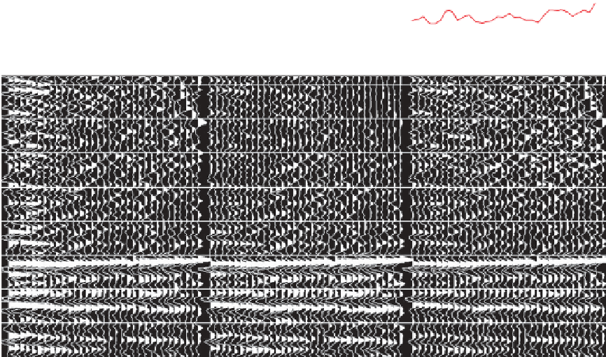
Figure 6.7
Example of a final scaling step using long gate AGC. The AVO gradient on the arrowed event is distorted by the high amplitude
of the near traces if no scaling is applied, but as the AGC window narrows the AVO gradient flattens.
angle range available. Usually it is possible to make
use of near angle data down to the lowest angle
available at the level of interest (which is usually a
few degrees as the shortest source
angle range into equal parts. So, for example, three
angle stacks to be made from data with a range of
3° to 39° would each cover a range of 12° in incidence
angle. For the purposes of AVO inversion a smaller
angle range is often considered ideal. For example,
around 7° might be more appropriate, suggesting that
in this case five angle stacks should be generated.
Since narrow-range stacks will tend to be noisy, it is
worth considering application of a noise-reduction
process such as structure-oriented filtering (Höcker
and Fehmers,
2002
; Helmore et al.,
2007
).
-
receiver offset
available is not zero). In many instances, angle ranges
of angle stacks generally conform with the angle range
over which the change of amplitude with sin
2
is
linear, so that two term (e.g. intercept/gradient) inter-
pretation techniques may be applied to the data.
Ideally the processor would check the linearity of the
amplitude response (in general linearity holds to an
incidence angle of around 30°). Certainly the inter-
preter needs to be careful that direct arrival and
refraction energy has been omitted from far stacks.
Sometimes there is considered to be useful data
beyond the angles at which amplitudes vary linearly
with sin
2
θ
6.3 Data conditioning for AVO analysis
In summary, the steps that may be needed to condi-
tion seismic data for AVO analysis are:
θ
and this data may be used to create an
conversion to angle gathers
'
stack. The interpretation of ultra-far stacks
can be fraught with uncertainty owing to the potential
for interplay of imaging and geological effects, includ-
ing anisotropy.
Having defined the useful range a usual approach
would be to stack near and far or near, mid and far
stacks for general interpretation use by dividing the
ultra-far
'
spectral equalisation
residual moveout removal
residual scaling of amplitude with offset (offset
balancing).
The first step is to convert the offset gathers to angle
gathers, so that each trace represents the seismic
118