Geoscience Reference
In-Depth Information
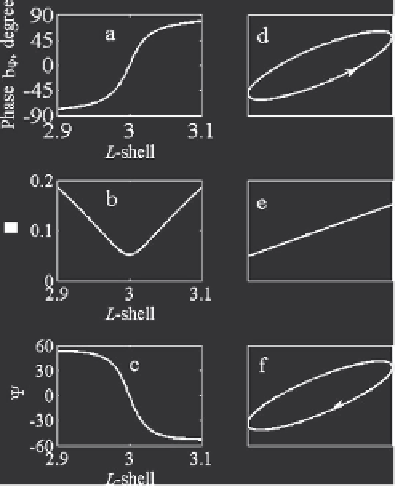
Fig. 6.12.
(a) Dependency of the
b
ϕ
(
L
)-phase; (b) ellipticity
(
L
) and (c) phase
shift
Ψ
(
L
) between the normal to magnetic shell component
b
ν
and azimuthal com-
ponent
b
ϕ
. The plots are calculated close to the resonance shell. The panels (d),
(e) and (f) demonstrate sequential changes of the rotation sign of the polarization
ellipse passing through the FLR-shell. (d) shows elliptical polarization and counter-
clockwise rotation of the transversal magnetic field within the FLR-shell at
T<T
r
,
(e) linear polarization at the shell,
T
=
T
r
and (f) the elliptical polarization with
clockwise rotation of the transversal magnetic component outside the shell,
T>T
r
3
/L
r
)
−
1
/
2
and
m
is the azimuthal wavenumber.
The rotation of the polarization ellipse is determined by the phase shift
Ψ
between the transversal magnetic components:
Ψ
=arg
b
ν
b
ϕ
where
ξ
=(
L
r
/L
−
1) (4
−
=
π/
2+arg(
ξ
) + arg[ln
|
mξ
|
+
i
(
−
π/
2+arg(
ξ
))]
.
Figure 6.12 demonstrates the dependencies of the magnetic field polarization
close to the resonance magnetic shell
L
=
L
r
as functions of
L.
In this example
L
r
= 3. Spatial distribution of the
b
ϕ
-phase is shown in Fig. 6.12
a
.The
ellipticity
(
L
) and the phase shift
Ψ
(
L
) are shown in the frames (b) and
(c) respectively. The frames (d), (e) and (f) demonstrate sequential changes
of the rotation sign in the polarization ellipse at the transition through the
FLR-shell. Herewith, (d) shows elliptical polarization and counter-clockwise
rotation of the transversal magnetic field within the FLR-shell at
T<T
r
,(e)
linear polarization at the shell,
T
=
T
r
and (f) the elliptical polarization with
clockwise rotation outside the shell,
T>T
r
.
Search WWH ::

Custom Search