Biomedical Engineering Reference
In-Depth Information
Not all CRT systems have all configurations available.
Because of an increased risk of LV lead dislocation, sufficient
safety reserve over the pacing thresholds must be pro-
grammed for pacing pulses, although it could adversely
affect the longevity of the device , which already is reduced
by permanent pacing.
11.2
CRT Pacing Con fi guration
The configuration of LV lead electrodes provides enhanced
programmable pacing and sensing capabilities in the LV
channel. Proper programming of LV lead configuration may
optimize the operation of the CRT system in terms of electri-
cal as well as clinical parameters. Unipolar, bipolar, or
extended bipolar configurations are available. The options
depend on the features of the CRT device and the polarity of
the implanted lead.
In justified cases, the LV channel can be left temporarily
or permanently unconnected, for example, if the lead cannot
be placed in an optimal manner, if later epicardial implanta-
tion is planned, or if the lead gets loosened and dislocated, or
if it is decided to leave the lead implanted and connected but
unused.
In some manufacturers' systems, the LV lead can have dif-
ferent pacing and sensing configurations, which allows pac-
ing or sensing to be optimized by the selection of the highest
sensed signal or the lowest pacing threshold. The LV lead
pacing vector can also affect the resulting width of a biven-
tricularly paced QRS complex, which we aim to minimize.
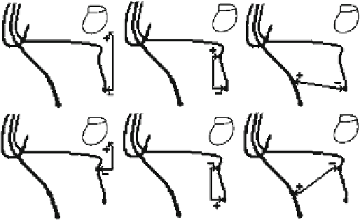
When using a bipolar LV lead, six pacing and sensing
configurations can be programmed (Fig.
11.1
):
LV distal electrode
11.3
CRT Timing
To ensure optimum CRT delivery, appropriate device param-
eter values and pacing timing must be programmed. As far as
CRT systems are concerned, permanent pacing of the right
and left ventricle is considered optimal. Programming the
device for separate RV pacing is not intended for the treat-
ment of heart failure; rather, it worsens the situation. LV pac-
ing has not yet been recognized as a clinically valid method
to treat heart failure. This must be taken into consideration
when setting the timing and parameters. In addition to AV
delay, most manufacturers' systems also include interven-
tricular (VV) delay (between RV and LV events in CRT).
If the patient's intrinsic heart rate drops below the LRL,
the device delivers pacing pulses at the LRL. If the patient's
intrinsic rhythm is lower than the MTR and the programmed
AV delay value is lower than the time of intrinsic AV con-
duction, the device applies pacing pulses in both ventricles
according to the programmed setting. To ensure maximum
biventricular pacing, the value of AV delay must be set lower
than the patient's intrinsic PR interval.
For the purpose of decision making concerning the CRT
or bradycardia therapy, a cardiac cycle based on RV sensed
or paced events is used and to which all device timing cycles
are related. Sensed LV events suppress inappropriate LV
pacing and have no influence on the timing cycle. This allows
CRT to be applied even in the VVI mode without an atrial
lead, for example, in the case of chronic atrial fibrillation.
The parameter of sense AV delay is used to reach a shorter
AV delay after sensed atrial events, whereas the programmed
value of the pace AV delay parameter is used after paced
atrial events. Atrial pacing can prolong the interatrial delay,
which is why it can be necessary to program various AV
delay parameter settings to optimize CRT during sensed and
paced sinus rhythm. Setting optimal AV delay parameters
should result in the maximization of the LV filling time. This
should be verified after implantation by means of echocar-
diography or pulse pressure monitoring. The optimized value
is often around 100 ms.
Because of the extension of the pacing system with an LV
lead, the CRT system is also supplemented with blanking and
refractory periods [ 77, 82 ] . These periods (Fig.
11.2
), how-
ever, are not programmable in all manufacturers' systems. For
example, the LV refractory period (LVRP) prevents the unde-
sirable loss of CRT after a sensed or paced event, such as a left
T wave. Proper programming of this function helps maximize
-
device (unipolar)
LV proximal electrode
-
device (unipolar)
-
LV distal electrode
LV proximal electrode (bipolar)
LV proximal electrode
-
LV distal electrode (bipolar)
-
LV proximal electrode
RV proximal electrode (extended
bipolar)
LV distal electrode
-
RV proximal electrode (extended
bipolar)
When using a quadripolar lead, ten pacing configurations
can be programmed in this commercially available system.
Theoretically, this number could be increased to 14 if unipo-
lar configurations were used.
Fig. 11.1
LV lead con fi gurations [ 82 ] (© 2012 Boston Scienti fi c
Corporation or its affiliates. All rights reserved. Used with permission
of Boston Scienti fi c Corporation)