Biomedical Engineering Reference
In-Depth Information
Fig. 10.5
De fi brillation waveform
•
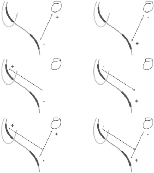
RVC-SVC-can. This vector makes use of the ICD metal
can as an active electrode in combination with a dual-coil
defibrillation lead. Current density creates a double path-
way from the distal electrode on the shock lead to the
proximal electrode and the ICD can.
Defibrillation waveform parameters are crucial for the
efficacy of defibrillation. In principle, we distinguish between
a monophasic and biphasic defibrillation waveform with
characteristic values, per Fig.
10.5
. Several characteristic
values may be identified in the defibrillation waveform. In
the amplitudes:
Positive phase leading-edge voltage V1 (V)
Fig. 10.4
De fi brillation con fi gurations [ 82 ] (© 2012 Boston Scienti fi c
Corporation or its affiliates. All rights reserved. Used with permission
of Boston Scienti fi c Corporation)
-
-
Positive phase tilt V2 (%)
-
Negative phase leading-edge voltage V3 (V)
-
Negative phase tilt V4 (%)
re-formation. During idle time, a capacitor may be deformed,
which may result in the charging time being prolonged
slightly. The shock energy remains constant throughout the
longevity of the device, regardless of changes to the lead
impedance or battery voltage.
The waveform polarity refers to the relationship between
values of the voltage of the leading edge of the defibrillation
pulse at the output of the lead defibrillation electrode.
Changing the polarity by physically swapping a lead cathode
and anode on the ICD output is prohibited. A programmable
function must always be applied. Switching the physical
polarity may result in damaging to the device or postopera-
tive nonconversion of the arrhythmia.
When using a defibrillation lead with two coils (right ven-
tricular coil [RVC]; supraventricular coil [SVC]), three shock
vector configurations are programmable (Fig.
10.4
):
RVC-can. This vector makes use of the ICD metal can as
In the time domain:
Positive phase duration PW1 (ms)
-
-
Negative phase duration PW2 (ms)
Relative values of these parameters vary with individual
manufacturers. Absolute values are determined by set shock
energy, defibrillation circuit impedance, and nominal capac-
ity of the ICD capacitor. Positive phase leading-edge voltage
V1 at maximum energy exceeds 700 V. The greater the
capacity of the capacitor, the longer the PW1 time (the more
time is needed for discharge).
Manufacturers apply two methods to express shock energy:
delivered or stored. The delivered energy is the energy that
passes through output shock connectors and dissipates in a
patient or par value resistance (50 Ω). Delivered energy will
always be lower than stored energy because a portion of the
stored energy dissipates even in the ICD. In addition, shocks
can be terminated before the entire energy stored in the capac-
itors is transferred. The delivered energy is a crucial quantity
for the determination of the ICD's efficacy.
•
an active lead. The energy passes from a distal shock elec-
trode to the ICD can via only one pathway. This
configuration must be chosen when using a lead with one
defibrillation electrode (single coil).
RVC-SVC. The vector does not make use of the ICD can
10.4
ICD Diagnostic Features
•
as an active lead. The energy passes from a distal shock
electrode to the proximal electrode. This vector must
never be used with a single-coil lead because a shock
would fail to be delivered.
The ICD automatically records information on the detection
and therapy for each detected tachycardia episode. Then, the
data can be searched through at various levels of detail using