Biomedical Engineering Reference
In-Depth Information
Fig. 8.1
Block diagram of
a dual-chamber pacemaker
Communication
Unit
RAM Memory
(diagnostics)
Input
Amplifiers (AGC)
Right
Atrium
Lead
Control
oscillator
Control Unit
Right
Ventricle
Lead
ROM Memory
Output
Amplifiers
electrode cathode. During the flow of pacing current, the
cathode attracts positively charged ions and repels negative
ions from the extracellular space. The cathode quickly sur-
rounds itself mainly by sodium ions, while negative ions
(e.g., chloride) are distant. Thus, two layers of oppositely
charged ions are formed in the myocardium, and the current
flow is caused by their movement. Capacity impedance
occurs as a consequence of the two ion layers. This capacity
effect grows during a pacing pulse with the peak on the trail-
ing edge, and it avoids charge movement in the myocardium.
Then, this increases the voltage required for pacing. The
polarization impedance is directly proportional to the width
of the pacing pulse and inversely proportional to the area of
the lead electrode, which is why pacing with the shortest
possible pulse and optimizing the surface of pacing elec-
trodes, as described in Chap. 7 , is recommended. With a lead
implanted in situ in the endocardium, the system impedance
is between approximately 200 and 2,000
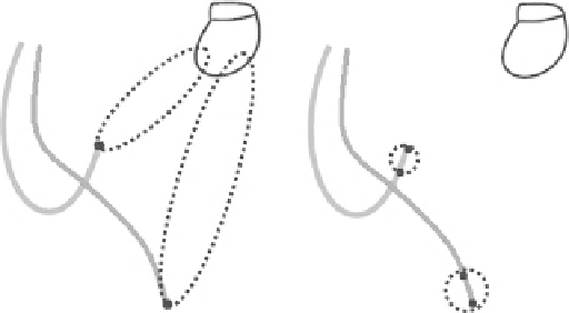
Fig. 8.2
Unipolar and bipolar con fi gurations
lead insulation. Because the devices are powered by batteries
with limited capacity, it is desirable to pace toward high
impedance, which will limit the output current to a deter-
mined voltage.
The total impedance is influenced by several factors
occurring on the pacing current pathway: the pure ohmic
resistance of the lead conductor, lead electrode, and the
myocardium themselves; and the polarization determined by
gathering charges of opposite polarity on the pacing elec-
trode and myocardium tissue interface. The lead conductor
resistance causes a decrease in the voltage along the lead and
partial heating of the lead. This poses an unnecessary loss of
energy; therefore, the lead conductor resistance should be
minimized. On the other hand, there should be strong resis-
tance in the lead electrode to minimize flowing current and
save the energy source. The pacing electrode resistance also
depends on its geometric arrangement - a smaller surface
provides higher resistance - but also higher current density
and thus lower pacing threshold. The polarization imped-
ance is the last component; it is determined by the move-
ment of charged ions in the myocardium to the pacing
. Parasitic capaci-
ties, inducing a polarization effect in the direction opposite
that of the pacing voltage, constitute an imaginary compo-
nent of the impedance [ 40 ] .
W
8.3
Basic Pacing Parameters
In the absence of intrinsic cardiac activity, the device paces
the heart at a certain rate determined by a parameter referred
to as the lower rate limit (LRL). The parameter is given in
pulses per minute (see Chap.
9
). LRL is also related to other
pacing parameters, and even to the tachycardia zone setting.
Certain systems allow decelerated pacing at night, that is,
when it is assumed the patient is asleep and the heart rate
decreases to the lowest level. At the beginning of the night
mode, the pacing gradually decreases to the lowest level, and
at the end, it gradually increases again to the daytime level.