Biomedical Engineering Reference
In-Depth Information
1 V just on the lead conductor. The resistance of defibrillation
leads is much less because of the usage of conductors with a
larger diameter; the maximum is about 2 Ω.
7.1.4
Construction of Lead Connectors
In the early stages of the cardiac pacing, the incompatibility of
lead connectors and connector headers on a device was a tech-
nical problem. In those days, the necessary technical stan-
dards were neither created nor applied yet. Development went
through various socket joints and bayonet systems, to 5- to
6-mm unipolar or bifurcate bipolar connectors, and finally to
3.2-mm bipolar connectors. These connectors already con-
tained two double-tandem contacts for every pacing electrode.
Lack of unity also dominated in the area of seal plugs and
placement of liners. Some manufacturers left them at the lead
connector, others in the port of the device's connector header.
In this situation, manufacturers made a provisional agreement
dealing with a voluntary standard for lead connectors and seal
plugs and used a 3.2 mm connector (VS-1). Lasting problems
with the acceptability of this standard finally were solved by
the acceptance of the international technical standard for a
bipolar connector of the pacing lead, designated as IS-1
(Fig.
7.7
). It currently deals with the international standard
ISO 5841-3:2000 Implants for Surgery - Cardiac Pacemakers
- Part 3: Low-Profile Connectors (IS-1) for Implantable
Pacemakers
. The connector is tubular to enable introduction
of the stylet or guide wire. The standard currently is used for
cardiac pacing leads. Despite this standard, when heart resyn-
chronization therapy was put into wider practice, a specific
connector - type LV-1 - was designed for the left ventricular
lead in which the seal plugs are placed in a port on the device
header instead of on the lead connector. This enabled the cath-
eter used to access the coronary sinus to be pulled over the
lead connector in the case of dislocation of the left ventricular
lead that was previously applied. However, when the
proficiency in insertion of the left ventricular leads increased,
the usage of this connector was terminated.
The international standard for the connector of one elec-
trode of the DF-1 defibrillation lead is
ISO 11318:2002
Cardiac Defibrillators - Connector Assembly DF-1 for
Implantable Defibrillators - Dimensions and Test
Requirements
. According to whether it uses one or two shock
electrodes, the defibrillation lead might be equipped with
two (IS-1 + DF-1) or three (IS-1 + 2 × DF-1) connectors. The
DF-1 connector is unipolar only and it is not tubular.
In connection with the miniaturization of the dimensions
of implantable cardioverter-defibrillators and cardiac resyn-
chronization therapy for defibrillators and with the reduction
of the mechanical connection of leads to the device connec-
tor header, an effort was made to deal with the elimination of
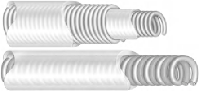
Fig. 7.5
Coaxial and co-radial lead conductor designs
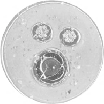
Fig. 7.6
Cross section of a de fi brillation lead
for defibrillation, according to whether it deals with a lead
with one or two defibrillation shock electrodes. Regarding
their construction, defibrillation leads are divided into inte-
grated bipolar leads, which include electrically connected
electrodes (the proximal pacing electrode and the distal
shock electrode), and separated bipolar leads, in which the
electrodes are separated. The conductors are insulated by, for
example, tetrafluoroethylene in isolated channels inside the
body of the lead, which is made of silicone rubber. The sec-
ond layer of insulation covers the lead body and ensures
additional insulation and a unique diameter (see Fig.
7.6
).
The most liable place for mechanical damage of the
implanted lead is usually near the crossing of the subclavian
vein and the first rib. Fixation that is too strong at the point
where the lead enters into the vein might damage the insula-
tion, especially if a suture sleeve (lead protector) is not used
for the suturing.
The lead conductor, together with the pacing electrodes,
predominantly designate the electrical properties of the lead.
The total electrical resistance of the conductor between the
connectors and pacing electrodes might range from about
30 to 150 Ω. It depends on the lead length. This value is not
negligible, and it creates a considerable part of the impedance
value within the pacing circuit. With pacing by a current of,
for example, about 7 mA, there is a decrease in voltage up to