Biomedical Engineering Reference
In-Depth Information
D
T
2
T
1
Fig. 3.4
Optical isolation circuit using LOC 110
modulated signal is converted back to analog voltage by an averaging technique.
The functional block diagram of a capacitive IsoA is shown in Fig.
3.5
. However,
in capacitive isolation also, the use of separate isolated power supply is mandatory.
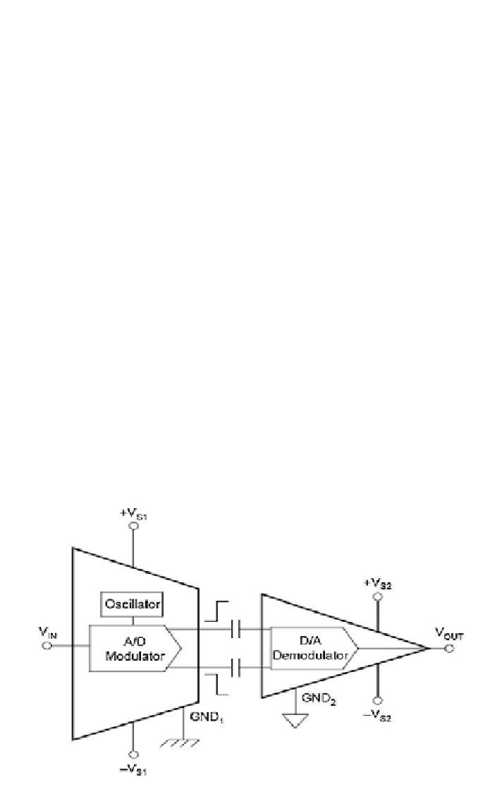
In some variants of capacitive IsoA, the input is modulated to a duty cycle encoded
signal (Burr-Brown ISO103, ISO107, ISO121), while in others, it is converted to
frequency (Burr-Brown ISO102, ISO106).
The performance of an isolation amplifier is described by isolation-mode
rejection ratio (IMRR), which refers to its ability to suppress the feed-through
isolation-mode voltage that arises across the barrier and output stage, detailed
in [
24
].
Accidental voltage surge protection from the biomedical equipment can be
achieved by connecting voltage-limiting devices (e.g., zener diode) between the
connecting electrode and ground. The device absorbs the extra current inrush when
the voltage across it raises a certain value, typically 300 mV or higher.
Fig. 3.5
Block diagram of capacitive isolation amplifier

Search WWH ::

Custom Search