Biomedical Engineering Reference
In-Depth Information
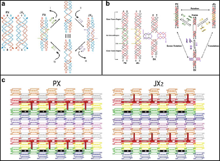
Fig. 11.8
(
a
) Schematic graph of the PX and JX
2
motifs and the principles of device operation
(Reprinted by permission from Macmillan Publishers Ltd: Ref. [
52
], copyright 2002). (
b
)
Schematic graph of the PX, JX
2
, and BX motifs and the principles of the three-state device
operation (Reprinted from Ref. [
53
]). (
c
) The schematic arrays of the two states of the device
in the cassette (From [
55
]. Reprinted with permission from AAAS)
gel electrophoresis, and AFM. Furthermore, a construction of a pair of reciprocal
PX-JX
2
devices has been developed, in which the two devices can be controlled in
parallel by the same set of effector strands [
54
]. In this system, the same set strands
put device I in PX state while putting device II in JX
2
state. The addition of the same
fuel strands results in the PX-JX
2
transition for device I, and JX
2
-PX transition for
device II. This is one of the first examples in which two independent devices can be
operated in parallel at the same time.
In another approach, Ding and Seeman developed a cassette obsessing three
features that are PX-JX
2
device function, state indication by a reporter helix, and
ability of insertion into a 2D DNA array (Fig.
11.8
c) [
55
]. In the context of a
DNA tile, the switch between PX and JX
2
conformation of the cassettes was clearly
visualized on AFM by discriminating the orientation of the reporter helix relative to
the marker tile. A similar approach was conducted on a DNA origami system [
56
].
Two PX- JX
2
cassettes are attached to the DNA origami, and four capture molecules
are predesigned to have sticky ends with primed labels that are complementary to
the pairs of sticky ends on the cassettes. Each of the four state combinations of
the two cassettes encodes an individual capture molecule, which presents a unique
morphology on AFM.
Search WWH ::

Custom Search