Biomedical Engineering Reference
In-Depth Information
different walking and running speeds (Romero et al., 2011). Energy
harvesters can then be designed to scavenge this energy for powering
portable electronics or implantable biomedical devices.
2.3 POWER LIMITS
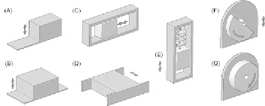
Energy harvesting generators harnessing motion typically follow a
cantilever-beam architecture with a proof mass at the end of the beam,
although several other geometries are also used, as shown in
Figure 2.1
. This approach that uses a proof mass are known as inertial
or kinetic energy harvesting. The transduction from kinetic energy to
electrical energy usually consists of electromagnetic, piezoelectric, or
electrostatic technique. Electromagnetic generation uses the relative
displacement between a magnet and a coil to induce a voltage; piezo-
electric generation uses the straining of the material to produce a volt-
age; whereas electrostatic transduction uses the changing distance of
the parallel plates of a capacitor (or change of dielectric properties) to
increase the voltage (potential energy) of a charged capacitor.
Mitcheson et al. (2004b) classified the kinetic generators according to
the damping mechanism used. Hence, generators are classified accord-
ing to the damping by a force proportional to the velocity, velocity-
damped resonant-generators (VDRGs), or by a constant force,
Coulomb-damped resonant-generators (CDRGs). Coulomb-force
parametric-generators (CFPGs) is the category for nonresonant gen-
erators damped by a constant force. Electromagnetic and piezoelectric
transductions are the common methods for VDRGs, while CDRGs
and CFPGs usually employ electrostatic transduction.
Figure 2.1 Energy harvester geometries: (A) cantilever beam, (B) out-of-plane plate, (C) free-sliding mass,
(D) in-plane plate, (E) springmass system, (F) oscillating rotational, and (G) continuous rotation generator.
Designs adapted from Yeatman et al. (2007) and Arnold (2007).