Biomedical Engineering Reference
In-Depth Information
(a)
(b)
(c)
(d)
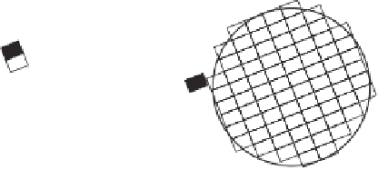
Figure 6.6
Possible effects of droplet crystallization on solute distribution. Solute is shown schematically
as filled rectangles and crystalline carrier lipid as open rectangles. (a) The solute may be incorporated into
the crystal lattice. On the other hand, if the solute is excluded from the lattice it can accumulate (b) at grain
boundaries inside the droplet, (c) at the surface of the droplet or even (d) partition into the aqueous phase.
Note the droplets are drawn as spheres although different shapes are possible as discussed previously.
(Highly schematic and not to scale.)
unlikely event where phase separation does not follow lipid crystallization, that is, the BLI
can form a single solid phase with the carrier lipid. Co-crystallization would presumably be
detectable as large shifts in the XRD but unsurprisingly, considering the wide disparity in
molecular shapes of solute and solvent, co-crystallization appears to be uncommon. For
example, Bunjes and co-workers (2001) found no evidence that ubidecarenone was
incorporated into the lattice of SLN although the kinetics of polymorphic transition in the
lipid increased in the presence of the drug. It may, however, be possible to form compound
crystals if the BLI of interest is itself a TAG (Takeuchi
et al
., 2002 a, 2002 b). Presuming
co-crystallization is the exception rather than the rule, then some level of phase separation
must occur and the question becomes where are the separate phases localized?
Figures 6.6b, 6.6c and 6.6d show a phase separation of the BLI as either a solid precipitate
or as a solution with residual liquid lipid. In Figure 6.6b, the BLI is entrapped within the
solid droplet; in Figures 6.6c and 6.6d, the BLI is excluded from the crystalline lipid core
and either adsorbed at the surface or dispersed in the aqueous phase, respectively. The major
thermodynamic difference between the models is that the surface-bound model (Figure 6.6c)
has more crystalline lipid-BLI interactions and fewer water-BLI and water-crystalline lipid
interactions than the BLI-excluded model (Figure 6.6d). While there may be some
exceptions, the surface-bound model is probably energetically preferable in most cases. In
conclusion, amongst the models presented for BLI encapsulation in Figure 6.6 the core-
trapped (Figure 6.6b) and surface-bound (Figure 6.6c) seem the most probable. The most
likely suitable location for entrapment in the solid droplet core (i.e., Figure 6.6b) is the grain
boundaries between TAG crystals or simply dissolved in any residual liquid oil.


Search WWH ::

Custom Search