Biomedical Engineering Reference
In-Depth Information
x
2
, X
II
(11, 9)
(8, 7)
t = 2
(9, 6)
5
(6, 5)
(4, 4)
(6, 4)
t = 1
(5, 3)
(3, 2)
1
t = 0
x
1
,
X
I
0
0
1
5
10
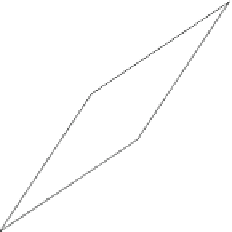
Fig. 2.3
The movement of a square at
t
¼
0 due to the motion (
2.12
)
unit square whose corners are at the material points (
X
I
,
X
II
)
¼
(0, 0), (
X
I
,
X
II
)
¼
(1, 0), (
X
I
,
X
II
)
¼
(1, 1), (
X
I
,
X
II
)
¼
(0, 1). At
t
¼
0 the motion (
2.12
) specifies that
x
1
¼
X
I
,
x
2
¼
X
II
, and
x
3
¼
X
III
so that
t
¼
0 has been taken as the reference
configuration. The square at
t
¼
0 is illustrated in Fig.
2.3
.At
t
¼
1 the motion
(
2.12
) specifies the places
x
of the particles
X
as follows:
x
1
¼
2
X
I
þ
X
II
þ
3
;
x
2
¼
X
I
þ
2
X
II
þ
2
;
x
3
¼
X
III
:
Thus the particles at the four corners of the unit square have the following new
places
x
at
t
¼
1:
ð
3
;
2
Þ¼wð
0
;
0
Þ; ð
5
;
3
Þ¼wð
1
;
0
Þ; ð
6
;
5
Þ¼wð
1
;
1
Þ; ð
4
;
4
Þ¼wð
0
;
1
Þ:
A sketch of the deformed and translated unit square at
t
¼
1 is shown in Fig.
2.3
.
At
t
¼
2 the motion (
2.12
) specifies the places
x
of the particles
X
as follows:
x
1
¼
3
X
I
þ
2
X
II
þ
;
x
2
¼
2
X
I
þ
3
X
II
þ
;
x
3
¼
X
III
:
6
4
Thus the particles at the four corners of the unit square have the following new
places at
t
¼
2:
ð
6
;
4
Þ¼wð
0
;
0
Þ; ð
9
;
6
Þ¼wð
1
;
0
Þ; ð
11
;
9
Þ¼wð
1
;
1
Þ; ð
8
;
7
Þ¼wð
0
;
1
Þ:
A sketch of the deformed and translated unit square at
t
¼
2 is shown in Fig.
2.3
.


Search WWH ::

Custom Search