Biomedical Engineering Reference
In-Depth Information
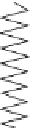
Fig. 1.11
The standard linear
solid
F
η
k
k
R
element under the same loading, there is no instantaneous deflection, but a creeping
deflection begins under the constant applied stress and proceeds asymptotically to a
rest value. There is only one lumped three-parameter element of interest, the
standard linear solid (SLS, Fig.
1.11
).
Example 1.8.2
Using the Fig.
1.11
as a guide, derive the differential equation of the governing
force-deflection relationship of the standard linear solid.
Solution
: Let
F
L
and
F
R
denote the force in the two branches, left and right, of the
standard linear solid; the total force
F
is then given by
F
F
R
. Let
x
denote
the overall deflection of the standard linear solid element; the deflections in both
branches must be equal; the horizontal cross-bars in spring-dashpot models are not
allowed to rotate. The total deflection in the right branch is the sum,
x
, of the
deflection of the dashpot,
x
D
, and the deflection of the spring,
x
S
; thus
x
¼
F
L
þ
x
S
.
The equations describing the behavior of the three constituent elements are
F
L
¼
¼
x
D
þ
(d
x
D
/d
t
), respectively. Note that the force in the
two elements on the right branch must be the same. These equations are combined
in the following manner. First, note that from
F
R
¼
kx,F
R
¼
k
R
x
S
and
F
R
¼
k
R
x
S
it follows that (d
x
S
/d
t
)
¼
(1/
k
R
)(d
F
R
/d
t
), from
F
R
¼
(d
x
D
/d
t
) it follows that (d
x
D
/d
t
)
¼
(1/
)
F
R
, and
from
x
¼
x
D
þ
x
S
it follows that (d
x
/d
t
)
¼
(d
x
D
/d
t
)
þ
(d
x
S
/d
t
). Combining these
results it follows that
(d
x
=
d
t
Þ¼ð
1
=Þ
F
R
þð
1
=
k
R
)(d
F
R
=
d
t
Þ:


Search WWH ::

Custom Search