Biomedical Engineering Reference
In-Depth Information
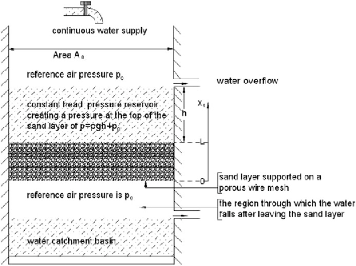
Fig. 1.8
An illustration of an experimental determination of the permeability of a sand layer
q
¼k ð@
p
=@
x
Þ;
(1.6)
where
L
has been replaced by the coordinate
x
in the formation of the one-
dimensional gradient operator. The minus sign is placed in (
1.6
) so that the
permeability
is positive. The fluid flow is always from regions of higher fluid
pressure to regions of lower fluid pressure, hence the pressure gradient in (
1.6
)is
always negative. The combination of the minus sign in (
1.6
) and the always-
negative pressure gradient mean the volume flow rate q is always positive.
The constitutive idea of the permeability element (Fig.
1.6c
) is that of a
distributed volumetric resistance to flow throughout the layer thickness
L
of the
porous medium. When a compressive force
F
is applied to the piston of the
permeability element, the water in the chamber under the piston is subjected to a
higher pressure and a pressure difference
p
k
p
o
is created between the inside of the
chamber and the air pressure
p
o
outside. The water in the chamber then flows from
the high-pressure region
p
þ
p
o
to the low-pressure region
p
o
and it passes out of
the chamber through the hole in the piston. This process continues until all the water
has been ejected from the chamber, the piston has moved to the bottom of the
cylinder and the chamber no longer exists. The volume flow rate q is the uniform
fluid velocity over the cross-section
A
o
of the orifice in the piston. The pressure
þ
Search WWH ::

Custom Search