Biomedical Engineering Reference
In-Depth Information
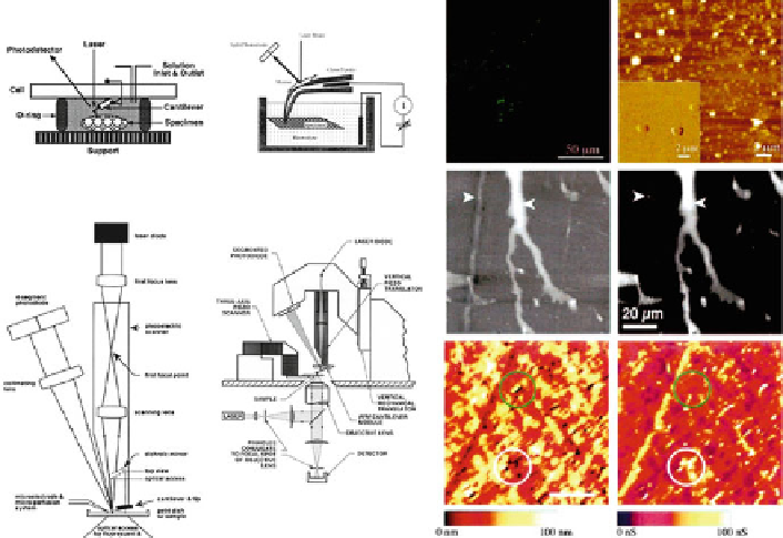
Fig. 2
Schematic setups of multimodal AFM systems (
left
), showing (clockwise from
top left
)
liquid cell, ionic conductance measurement setup, AFM integrated on optical confocal fl uores-
cence microscope, and lens-tracking system for systems with tip attached to scanner. The
right
panel
images show combined AFM and light fl uorescence microscopy images of amyloid beta
reconstituted vesicles (
top
), combined AFM and confocal fl uorescence microscopy images of fl uo-
rescently labeled latex beads dried into a gel on a plastic diffraction grating (
middle
), and com-
bined AFM image and electrical recording of a nucleopore synthetic membrane (
bottom
). For
details, see Lal and Lin (
2001
)
2.5
Forces and Image Contrast in AFM
The defl ection of the cantilever in contact mode, and the damping of vibration
amplitude in tapping mode, is caused by a sum of attractive and repulsive forces.
The main repulsive force is due to the overlapping of electron orbitals between tip
and sample atoms. Dominant attractive force is a van der Waals interaction primar-
ily due to nonlocalized dipole-dipole interactions (Goodman and Garcia
1991
) .
Another strong attractive force component while imaging in air is the meniscus
surface force due to adsorbed water layers. In fl uids, consideration should be given
to electrostatic interactions between charges and sample and tip, and structural
forces, such as hydration force, solvation forces, and adhesion forces (Mechler et al.
2003
; Almqvist et al.
2004
; Thimm et al.
2005
). Lateral forces can be measured (by
torsional defl ection of the cantilever) and can be quite considerable (Meyer and
Amer
1990
). Such forces can be used to generate images that can give valuable
information on local surface chemistry differences, such as the detection of locally
oxidized thiols on a topography-free surface (Pavlovic et al.
2003
) . In tapping mode,