Graphics Programs Reference
In-Depth Information
2.
Click the Polysolid tool on the Modeling panel on the far left side of
the Home tab. AutoCAD may pause briefly as it loads the 3D specific
applications.
3.
At the
Command: _Polysolid 0′-4″, Width = 0′-0 1/4″,
Justification = Center Specify start point or [Object/
Height/Width/Justify] <Object>:
prompt, enter
H
↵
7
′
7-1/4
″↵
(
2318
↵
) to set the object height to 7
′
-7¼
″
(2318 mm). This is the
height where the inside faces of the exterior walls meet the roof.
The exterior walls are 6
″
(150 mm) thick, so the polysolid object
should be 6
″
(150 mm) thick as well.
4.
Enter
W
↵
and then
6
↵
(
150
↵
) at the Specify width < 0
′
-0 ¼
″
>: prompt.
5.
The Justification option determines the side of the polysolid for which
you will pick the endpoints. You will be picking the outside lines of
the cabin in a counterclockwise order, so the justification must be set
to Right. Enter
J
↵
R
↵
.
6.
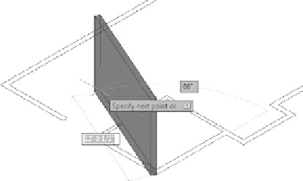
You're now ready to begin creating the walls. Use the Endpoint
osnap to select the corner for the exterior wall of the cabin nearest
to the bottom of the screen, and then move the cursor. The first wall
appears and it is tied to the cursor, as shown in Figure 16.10.
FiGuRE 16.10
Starting the first polysolid wall
7.
Moving in the counterclockwise direction, click each of the endpoints
along the outside perimeter of the cabin until only one segment sepa-
rates the last segment from the first. Your drawing should look like
Figure 16.11.
8.
Right-click and choose Close from the context menu to close the
polysolid.


Search WWH ::

Custom Search