Graphics Programs Reference
In-Depth Information
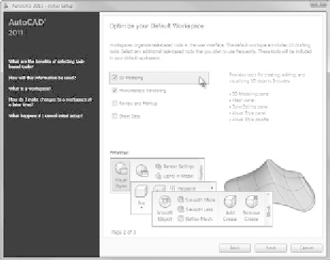
FiGuRE 16.3
Choosing the tool category in the second Initial Setup window
4.
In the third window, make sure Use AutoCAD 2011's Default Drawing
Template File is selected and then click Start AutoCAD 2011 (see
Figure 16.4).
If you started the Initial Setup Wizard using the
OPTIONS
command,
the Start AutoCAD 2011 button will be replaced with a Finish button.
5.
Open
14A-FPLAY1.dwg
; then use the Quick Views Layout button to
switch to model space.
6.
Zoom into the floor plan, make the A-WALL layer current, and freeze all
other layers. Your drawing and AutoCAD setup will look like Figure 16.5.
Try to start thinking of it in three dimensions. The entire drawing is
on a flat plane parallel to the monitor screen. When you add elements
in the third dimension, they project straight out of the screen toward
you if they have a positive dimension and straight through the screen if
they have a negative dimension. The line of direction is perpendicular
to the plane of the screen and is called the z-axis. You're already famil-
iar with the x- and y-axes, which run left and right and up and down,
respectively; think of the z-axis as running into and out of the screen.
7.
If the UCS icon isn't visible on your screen, click the View tab and then
click the Show UCS Icon button on the Coordinates panel.


Search WWH ::

Custom Search