Graphics Programs Reference
In-Depth Information
4.
Click the Model button in the status bar to switch from model space
to view the drawing through the layout. The appearance of the draw-
ing area changes to show a view into model space inside a white rect-
angle, sitting in front of a gray background.
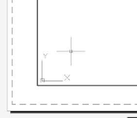
Your drawing has two borders along the perimeter of the white
rectangle (one dashed and one solid). If the UCS icon consists of two
arrows inside the solid border (see the left of Figure 14.16), then you
are currently working in model space. If the UCS icon is shaped like a
triangle and located in the portion of the drawing area (see the right
of Figure 14.16), then you are currently working in paper space. The
solid line is the boundary to the viewport, and the dashed line is the
limit of the printable area.
FiGuRE 14.16
The layout in model space (left) and when in paper
space (right)
TIP
You can switch back to paper space when working in model space
by moving your cursor outside of the inner, solid rectangle and double-
clicking, or by entering ps
↵
.
Setting the Layout Parameters
The paper shown—that is, the white rectangle—is the default size and orienta-
tion for the
ACAD.dwt
template. You'll need to set the parameters to utilize the
DWFx ePlot plotter (installed with AutoCAD).
1.
Click the Quick View Layouts button next to the Layout button in the
status bar to turn on the option. Small thumbnail representations of
the existing layouts appear at the bottom of the drawing area, as shown
in Figure 14.17.


Search WWH ::

Custom Search