Graphics Programs Reference
In-Depth Information
Any point on a graph can be specified by giving its coordinates relative to the
origin given as a combination of the X value and the Y value delineated with a
comma. For example, a coordinate of 5,7 means a point on the coordinate sys-
tem that is 5 units in the positive X direction and 7 units is the positive Y direc-
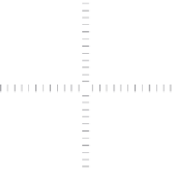
tion. Figure 2.11 shows a typical Cartesian Coordinate System and the default
region used as the drawing area in a new AutoCAD file.
NOTE
autoCaD displays a readout for the z-coordinate as well, but you
can ignore it for now because you'll be working in only two dimensions for the
majority of this topic. the z-coordinate always reads 0 until you work in three
dimensions. (This will be covered in the later chapters.) AutoCAD LT doesn't
have the readout for the z-coordinate because it doesn't have 3D capabilities.
Quadrant II
Quadrant I
0,0
Quadrant IV
Quadrant III
FiGuRE 2.11
The x- and y-coordinates of the drawing area
In this next exercise, you'll try using the
LINE
command again, but instead of
picking points in the drawing area with the mouse as you did before, this time
enter the x- and y-coordinates for each point from the keyboard. To see how to
do this, follow these steps:
1.
Click the Erase button from the Home
➢
Modify Ribbon panel,
O
2.
Enter
ALL
↵
. The objects in the drawing become dashed to indicate
that they are selected.
You can also start the
ERASE
command by
entering
E
↵
.
3.
Press
↵
to clear the screen.
4.
Click the Dynamic Input button in the command line to turn off this
feature. The button will change to a gray background.


Search WWH ::

Custom Search