Graphics Programs Reference
In-Depth Information
FiGuRE 13.37
The top of the Properties palette with the former xref selected
FiGuRE 13.38
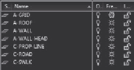
The Layer Properties Manager showing the new layers
7.
Click the Insert button in the Block panel of the Insert tab. In the
Insert dialog box, open the Name drop-down list.
13C-SPLAY1
is listed here as a block, along with the window and
door blocks that you created in Chapter 7 and the grid and north arrow
blocks. A few additional blocks might be on the list. These blocks are
used by the dimensions in the drawing.
8.
Close the drop-down list by clicking a blank portion of the dialog box.
Then click Cancel to return to your drawing.
The site plan is now a permanent part of the
13A-FPLAY3
drawing. If
you need to make changes to the site plan part of the drawing, you can
explode it and use the Modify commands. To edit the site plan while pre-
serving it as a block, you can use the
REFEDIT
(
Edit Reference In-Place)
command and
BEDIT
(Block Edit) tool that you used previously in
Chapter 7 to modify the window block.
9.
You do not want to save the changes in this drawing. Click the Close
button in the top-right corner of the drawing area, and then click No
in the dialog box that opens.
10.
Move the
13C-SPLAY1
file back into the
Training Data
folder where
it was prior to starting the exercises in the “Exploring Additional Xref
Features” section.


Search WWH ::

Custom Search