Graphics Programs Reference
In-Depth Information
5.
In the drawing area, click once to designate the lower-left corner of
the image, move the cursor, and then click again to create the rect-
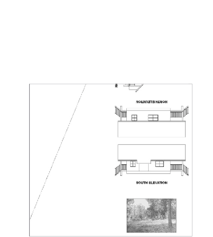
angular frame for the image.
The image appears inside the frame (see Figure 13.31). The exact
size and location of the frame are unimportant for this exercise, so
ignore them for now. In the next chapter, you will decide how to view
the image in the context of the rest of the drawing.
FiGuRE 13.31
Placing the referenced image in the drawing
The
IMAGEFRAME
variable determines the visibility of the image
frame and how it reacts when clicked. Setting the variable to
0
(zero)
causes the frame to be invisible and also prevents the image from being
selected or edited. Setting the variable to
1
displays the frame, allows
it to be selected, and also shows the frame when the drawing is plotted
(plotting is covered in Chapter 15, “Printing an AutoCAD Drawing”).
Setting
IMAGEFRAME
to
2
displays the frame in the viewport and allows
it to be selected, but it does not display the frame when the drawing is
plotted. This variable affects all the images in the drawing.
6.
Enter
IMAGEFRAME
↵
2
↵
to set the variable to
2
.
7.
Save the cabin drawing as
13A-FPLAY3.dwg
and then close the file.
Search WWH ::

Custom Search