Graphics Programs Reference
In-Depth Information
3.
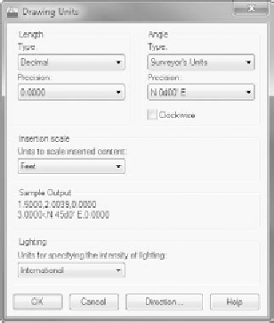
In the Angle area, open the Type drop-down list and select Surveyor's
Units. Then change the Precision value to the nearest minute (N 0d00
′
E).
4.
The floor plan drawings you have created so far defined each unit as
an inch. Because this is a civil/survey drawing, you'll change that by
making each drawing unit equal a foot.
Change the drawing Insertion Scale by changing the Units To Scale
Inserted Content drop-down list to Feet. Your Drawing Units dialog
box should look like Figure 13.4. Click OK.
FiGuRE 13.4
The Drawing Units dialog box set up to use surveyor's units
You'll need an area of about 250
′×
150
′
for the site plan.
5.
Set the Drawing Limits by entering
LIMITS
↵
at the command line.
Press
↵
to accept the default of 0.00,0.00 for the lower-left corner.
Enter
250,150
↵
. Don't use the foot sign.
6.
Enter
Z
↵
E
↵
, or double-click the middle mouse button to zoom to the
drawing's extents.
O
If the menu bar is
loaded, you can also
set the Drawing
Limits from the
Format menu.
7.
Create a new layer called
C-PROP-LINE
. Assign it the color number
172
and make it current.
8.
Turn on Dynamic Input in the status bar.
9.
Start the
LINE
command. For the first point, enter
220,130
↵
.
This starts a line near the upper-right corner of the grid.


Search WWH ::

Custom Search