Graphics Programs Reference
In-Depth Information
using the
Line
Command
In traditional architectural drafting, lines were often drawn to extend slightly past
their endpoints (see Figure 2.2). Today we have entire applications that can open
a CAD drawing and not only apply this effect, but make the drawing look hand
drawn. A popular application for applying such an effect is Autodesk Impression.
I won't be covering Autodesk Impression in this topic; however, you can visit
http://autodesk.com/impression
to
learn more about it.
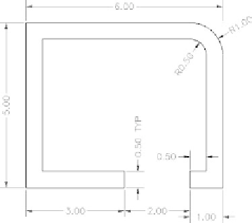
FiGuRE 2.1
The shape you'll draw
The
LINE
command draws a straight line segment between locations on existing
objects, geometric features, or two points that you can choose anywhere within the
drawing area. You can designate these points by left-clicking them on the screen,
by entering the x-
and y-coordinates for each point, or by entering distances and
angles from an existing point. After you draw the first segment of a line, you can
end the command or draw another line segment beginning from the end of the pre-
vious one. You can continue to draw adjoining line segments for as long as you like.
Let's see how this works.
To be sure that you start with your drawing area set up the way it's set up for
this topic, expand the Application menu (the red A button in the top-left corner
of the AutoCAD user interface), and then choose Close
➢
All Drawings to close
any open drawings. The Application menu is shown in Figure 2.3.
Like many other Windows-based programs, AutoCAD provides many ways you
can close drawings individually as well. The first and perhaps most popular way is
to click the X icon in the upper-right corner of any drawing next to the Minimize


Search WWH ::

Custom Search