Graphics Programs Reference
In-Depth Information
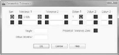
5.
Fill in the actual tolerance value(s) and datum references in the text
boxes, as shown in Figure 12.19.
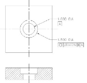
6.
When you're finished, click OK. You can insert the feature control
frame into your drawing like a block and reference it to a part or a
dimension, as shown in Figure 12.20.
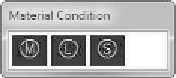
FiGuRE 12.18
The Material Condition dialog box
FiGuRE 12.19
The Geometric Tolerance dialog box with a few values provided
FiGuRE 12.20
Geometric dimensioning on a machined part
This exercise was intended to show you the tools that AutoCAD provides for set-
ting up the most commonly used lateral and geometric tolerances when you use the
Tolerances tab in the Modify Dimension Style dialog box and the Tolerance button
on the Dimensions panel. My intention here isn't to explain the methodology of
geometric tolerances or the meanings of the various symbols, numbers, and letters
used in them. That is a subject beyond the scope of this topic.


Search WWH ::

Custom Search