Graphics Programs Reference
In-Depth Information
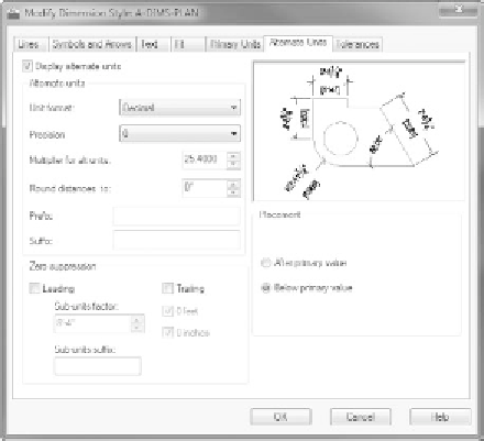
FiGuRE 12.13
The Alternate Units tab after being set up for millimeters
Exploring the tolerances tab
AutoCAD offers features with options that help you create several kinds of
toler-
ances
(allowable variances from the stated dimension). These are very common
in the machining and manufacturing industries, where it's understood that the
dimensions given are only approximations of the part fabricated. Tolerances are
usually measured in thousandths of an inch or hundredths of a millimeter. The
Tolerances tab provides four methods for creating what are called
lateral toler-
ances
, the traditional kind of tolerance that most draftspeople use. This is the
plus or minus
kind of tolerance. Open the Modify Dimension Style dialog box,
click the Tolerances tab, and look at the choices in the Method drop-down list,
shown in Figure 12.14.
Each of these is a method for displaying a plus or minus type of tolerance:
n o n e
No tolerances are displayed.
Symmetrical
This method is for a single plus or minus expression after the base
dimension. It's used when the upper allowable limit of deviation is identical to
that for the lower limit, as in 1.0625 ± 0.0025.
Deviation
This method is for the instance in which the upper allowable devia-
tion is different from that of the lower deviation. For example, the upper limit
of the deviation can be +0.0025, and the lower limit can be -0.0005. The two
deviation limits are stacked and follow the base dimension.

Search WWH ::

Custom Search