Graphics Programs Reference
In-Depth Information
12.
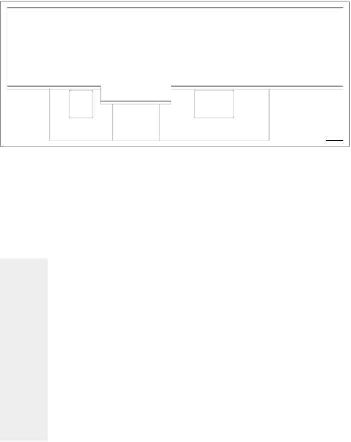
Complete the elevation view by using the
TRIM
command to trim
the two vertical lines representing the front and rear outside walls
to the roof soffit line. When finished the elevation should resemble
Figure 10.15.
13.
Save the current drawing as
10A-FPLAY2.dwg
.
FiGuRE 10.15
The completed elevation view
This is the basic process for generating an elevation: drop lines down from the
floor plan, and trim the lines that need to be trimmed. The trick is to learn to
see the picture you want somewhere among all the crossed lines and then to be
able to use the
TRIM
command accurately to cut away the appropriate lines.
t
I p s
F o r
U
s I n g
t h e
TRIM
a n d
EXTEND
C
o M M a n d s
TRIM
and
EXTEND
are sister commands. Here are a few tips on how
they work:
Basic operation
Both commands involve two steps: selecting cutting edges (
TRIM
) or bound-
ary edges (
EXTEND
) and then selecting the lines to be trimmed or extended.
Select the cutting or boundary edges first, and then press
↵
. Next, pick
lines to trim or extend. Press
↵
to end the commands. You can use the
Fence option or a selection window to select several lines to trim or extend
at one time.
(Continued)


Search WWH ::

Custom Search