Graphics Programs Reference
In-Depth Information
Close or auto-hide the Layer Properties Manager.
7.
Start the
INSERT
command (click the Insert button in the Block panel).
Open the Name drop-down list in the Insert dialog box.
In the list of blocks, click A-GLAZ. Be sure all three Specify On-Screen
check boxes are selected, and then click OK.
8.
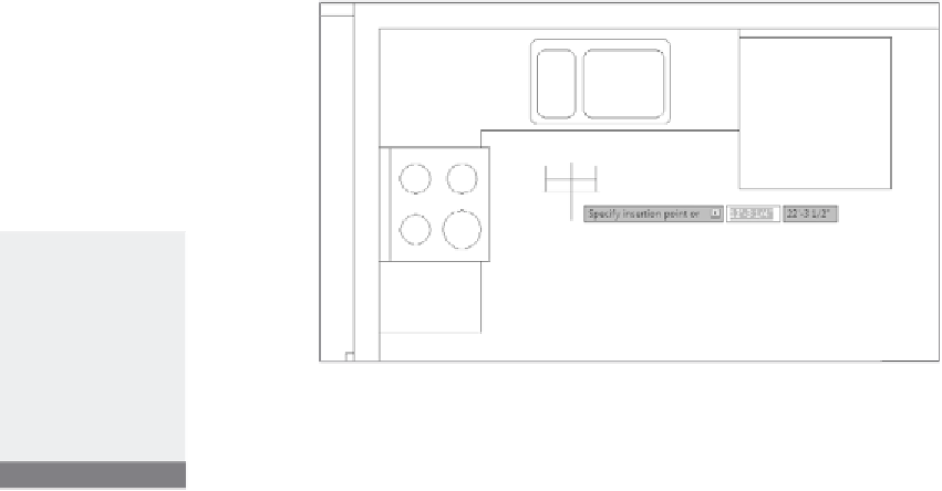
In your drawing, the 12
″
(305 mm) window block is attached to the
cursor at the insertion point (see Figure 7.31).
Note that it's still in the same horizontal orientation that it was in
when you defined the block. To it it into the left wall, you'll need to
rotate it as you insert it.
9.
Move the cursor along the inside wall line near the midpoint of the
stove. The stove line overlaps the wall line and the midpoints of each
are close together.
Make sure the cursor is over the stove's midpoint (the lower of the
two, as shown at the left of Figure 7.32), and then click.
10.
You're prompted for an X scale factor. This is a 4
′
-0
″
(1220 mm) win-
dow, so enter
4
↵
. For the Y scale factor, enter
1
↵
.
The window block is now 4
′
-0
″
(1220 mm), and you are prompted
for the rotation angle.
the Y scale fac-
tor will be 1 for all
the A-GLAZ blocks
because all walls
that have windows
are 6
″
wide—the
same width as the
A-GLAZ block.
FiGuRE 7.31
The A-GLAZ block attached to the cursor
11.
From the
Specify rotation angle
prompt, move the cursor so that
it's directly above the insertion point. The Polar Tracking lines and
tooltip appear (see the middle image of Figure 7.32).

Search WWH ::

Custom Search