Graphics Programs Reference
In-Depth Information
12.
Move to the right endpoint of the upper jamb line for the back door and,
with the same technique used in steps 6 through 10, draw the lower
header line across the opening. You can see the results in the left image
of Figure 6.37.
13.
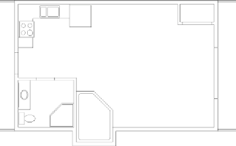
Keep using the same procedure to draw the rest of the header lines
for the remaining three doorway openings.
The floor plan will look like the right image of Figure 6.37.
14.
Save this drawing as
06A-FPLAY5.dwg
.
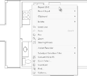
FiGuRE 6.36
A second right-click context menu with additional
commands available
FiGuRE 6.37
The header lines drawn for the back door opening (left) and
for the rest of the doorway openings (right)


Search WWH ::

Custom Search