Graphics Programs Reference
In-Depth Information
a
U t o
Cad lt U
s e r s
(Continued)
5.
Use the Endpoint osnap to select the lower-back corner of the stove.
The stove is completed as the remaining geometry is inserted into
the drawing.
Getting Started with Geometric Constraints
1.
Make sure
05A-FPLAY4.dwg
is open, and zoom into a closer view of
the stove.
2.
Select the current outline of the stove, and click the Auto Constrain
tool, found on the Parametric tab
➢
Geometric panel.
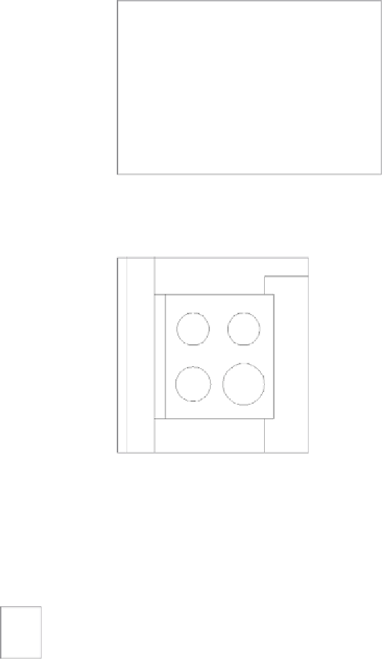
After you invoke Auto Constrain, a series of icons appear along the
perimeter of the stove, as shown in Figure 5.48. These icons illustrate
the geometric relationships AutoCAD established between the four
lines that define the outline of your stove.


Search WWH ::

Custom Search