Graphics Programs Reference
In-Depth Information
(millimeters) and divisible by 2. The dimensions of the outside wall line are 28
′×
16
′
(8550 mm
×
4850 mm) and the exterior walls are 6
″
(150 mm) thick. Here's how:
1.
Right-click the Grid Display button on the status bar, and click
Settings to open the Drafting Settings dialog box one more time.
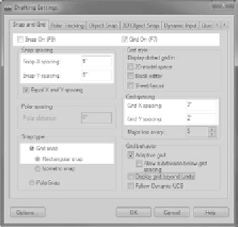
The Drafting Settings dialog box opens and the Snap And Grid tab is
active. The settings in both the Grid and Snap areas include X and Y
Spacing settings. Notice that they're all set for a spacing of ½
″
(10).
2.
In the Grid Spacing area, click in the Grid X Spacing text box and
change ½
″
(10) to 2
′
(1000) as shown in Figure 3.12. Then click in the
Grid Y Spacing text box. It automatically changes to match the Grid
X Spacing text box. If you want different Grid X and Grid Y Spacing
values, you must uncheck the Equal X and Y Spacing option in the
Snap Spacing area.
If you set the Grid
Spacing to 0, the
grid takes on what-
ever spacing you
set for the Snap
X Spacing and
Snap Y Spacing
text boxes. this is
how you lock the
snap and grid
together.
3.
In the Snap section, change the Snap X Spacing setting to 6 (50) as
shown in Figure 3.12. The inch sign isn't required. Then click the
Snap Y Spacing input box or press the Tab key. The Snap Y spacing
automatically changes to match the Snap X Spacing setting.
4.
In the Snap Type area, be sure Grid Snap and Rectangular Snap are
selected (Figure 3.12).
5.
In the Grid Behavior area, only Adaptive Grid should be checked.
With the grid set this way, AutoCAD will adjust the number of grid-
lines displayed as you zoom in and out, but it won't add gridlines
between the lowest grid spacing.
FiGuRE 3.12
New settings on the Snap And Grid tab of the Drafting Settings dialog box
using Imperial units (left) and Metric units (right)


Search WWH ::

Custom Search