Graphics Programs Reference
In-Depth Information
positive angular displacement goes in the counterclockwise direc-
tion. (See Figure 2.14 in Chapter 2 for an illustration of the Cartesian
Coordinate System.) These are the standard settings for most users of
CAD. There is no need to change them from the defaults. If you want to
take a look, open the Direction Control dialog box, note the choices, and
then click Cancel. You won't have occasion in the course of this topic to
change any of those settings.
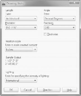
FiGuRE 3.4
The Drawing Units dialog box after changes
NOTE
You'll have a chance to work with the Surveyor's angular units
later in Chapter 12, “Dimensioning a Drawing,” when you develop a site plan
for the cabin.
4.
Click OK in the Drawing Units dialog box to accept the changes and
close the dialog box. Notice the coordinate readout in the lower-left
corner of the screen: it now reads in feet and inches.
This tour of the Drawing Units dialog box has introduced you to the choices
you have for the types of units and the degree of precision for linear and angular
measurement. The next step in setting up a drawing is to determine its size.
NOTE
If you accidentally click the mouse when the cursor is on a blank
part of the drawing area, autoCaD starts a rectangular window. I'll talk about
these windows soon, but for now just press the Esc key to close the window.


Search WWH ::

Custom Search