Graphics Programs Reference
In-Depth Information
Model view found on the status bar. When we get to later chapters, you'll
learn how to use the other tools, and in Chapter 10, “Generating
Elevations,” you'll see how to use templates to set up drawings.
2.
Choose Application Menu
➢
Drawing Utilities
➢
Units to open the
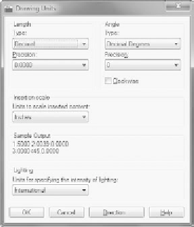
Drawing Units dialog box (
UNITS
command) shown in Figure 3.2.
In the Length area, Decimal is currently selected. Similarly, in the
Angle area, Decimal Degrees is the default.
3.
Within the Drawing Units dialog box, click the arrow in the Type drop-
down list found inside the Length group, and select Architectural (met-
ric users can leave this set to Decimal). These units are feet and inches,
which you'll use for the cabin project.
Notice the two Precision drop-down lists at the bottom of the
Length and Angle areas. When you changed the linear unit specifi-
cation from Decimal to Architectural, the number in the Precision
drop-down list on the left changed from 0.0000 to 0
′
-0
1
⁄
16
″
. At this
level of precision, linear distances are displayed to the nearest
1
⁄
16
″
.
Metric users should set this to 0 because we won't be using units
smaller than a millimeter.
O
You can also open the
Drawing Units dialog
box by typing
UN
↵
.
FiGuRE 3.2
The Drawing Units dialog box
4.
Select some of the other Length unit types from the list, and notice
the way the units appear in the Sample Output area at the bottom
of the dialog box. Then select Architectural again or leave it set to
Decimal for metric use.


Search WWH ::

Custom Search