Information Technology Reference
In-Depth Information
able to alter what we have stored. We can think of computer memory as being
like an array of mailboxes or pigeonholes (
Fig. 2.17
). Each box can store a data
value that can either be retrieved or replaced with a new value. Memory reg-
isters are just a set of electronic boxes that can store a pattern of bits. As with
logic gates, a wide variety of technologies have been used to implement com-
puter memory. From an abstract point of view, the specific technology does not
matter - in practice it matters a great deal, for reasons of reliability, speed of
access, and cost!
In the logic-gate circuits discussed in the preceding text, the output states
are completely determined by the inputs and the connections between the
gates. Such a circuit is called a “combinational circuit.” It is also possible to
construct another type of circuit - a “sequential circuit” - for which the out-
put of a device depends on the previous history of its inputs. A counter circuit
is an example of a sequential device where the current count number stored
is the sum of the number of pulses it has received. The elemental sequential
digital circuit is designed to be stable in one of two states. These “bistable ele-
ments” are usually called “flip-flops” - since they flip between the two states in
response to an input. The basic flip-flop circuit is important because it is used
as a memory cell to store the state of a bit. Register memories are constructed
by connecting a series of flip-flops in a row and are typically used for the inter-
mediate storage needed during arithmetic operations. Another type of sequen-
tial circuit is an oscillator or clock that changes state at regular time intervals.
Clocks are needed to synchronize the change of state of flip-flop circuits.
The simplest bistable circuit is the set-reset or RS flip-flop (
Fig. 2.18
). The
state of the flip-flop is marked as Q and is interpreted as the state
1
if the voltage
at Q is high or as 0 if the voltage is low. The complement of Q, Q , is also avail-
able as a second output. There are also two terminals that allow the flip-flop to
be initialized. The state Q can be set to 1 by applying a voltage pulse on the “set”
input S. A signal on the “reset” input R resets Q to 0.
Figure 2.18
shows an RS
flip-flop made out of NO
R
gates together with the corresponding truth tables. An
input signal S = 1 sets Q = 0 and if the input R = 0 then both inputs to the top
NOR gate are zero. Thus a signal on the set line S and no signal on R gives Q = 1.
This makes both inputs to the lower NOR gate 1. The other elements of the truth
table can be filled in by similar reasoning. Note that an input state with both R =
1 and S = 1 is logically inconsistent and must be avoided in the operation of the
flip-flop. So far, this RS flip-flop is still a combinational circuit because the state Q
depends only on the inputs to R and S. We can make this a sequential RS flip-flop
by adding a clock signal and a couple of additional gates (
Fig. 2.19
). The response
of the clocked RS flip-flop at time t+1, Q(t+1), now depends on the inputs and the
state of the flip-flop at time t, Q(t). A clock pulse must be present for the flip-flop
to respond to its input states. There are many other different types of flip-flops
and it is these bistable devices that are connected together to make registers,
counters, and other sequential logic circuits.
Nowadays computers make use of a whole hierarchy of memory storage,
built from a variety of technologies (
Fig. 2.20
). The earliest machines had only
registers for storing intermediate results, but it soon became apparent that
computers needed an additional quantity of memory that was less intimately
linked to the central processing unit (CPU). This additional memory is called
Fig. 2.16. We think of computers in
terms of today's technologies, which
use electronics and integrated circuits.
Computers can be constructed from
mechanical devices. This machine was
built by a group of students at MIT using
Tinker Toy spools and fishing line and
can play tic-tac-toe.
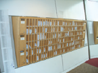
Fig. 2.17. Pigeonholes are a useful ana-
logy for a computer's memory.

Search WWH ::

Custom Search