Information Technology Reference
In-Depth Information
have replaced copper wires for high-bandwidth communications and made pos-
sible
the broadband
Internet we see today.
Broadband
has various definitions, but
the term now generally refers to high-speed data connections to the Internet.
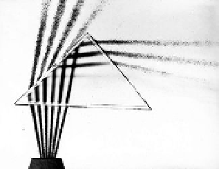
Optical fibers are thin “wires” of glass that transmit light using a phenome-
non called
total internal reflection
. We can see how such reflection comes about
by considering what happens when light travels from air into a block of glass.
Because light travels more slowly in glass than air, the light changes direction,
bending toward the vertical. This bending of light at a surface is called
refrac-
tion
. Now consider light traveling from glass to air, when the light bends away
from the vertical. If we increase the angle at which we shine light on the glass-
air surface, the transmitted ray emerges at an angle closer and closer to the
surface. At an angle called the
critical angle
, the light just grazes the surface. If
we increase the angle of incidence beyond this critical angle, all the light will
now be reflected and no light will escape into the air (
Fig. 10.20
). This is the
phenomenon of
total internal reflection
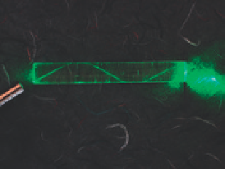
(see
Fig. 10.21
). It is this mechanism that
allows light to be transmitted down a glass fiber and to travel around bends in
the fiber.
Cladding
or covering (see
Fig. 10.22
) the core of the fiber with glass
of a lower refractive index provides a way to bend or reflect inward light rays
that strike its interior surface. This makes it possible for the light to travel long
distances with little loss of intensity. Durable optical fibers in medical imaging
devices like endoscopes carry light that enable doctors to examine the inside of
the stomach and other organs (
Fig. 10.23
).
Optical fibers were fine for use in applications like endoscopes where the
light only needs to be transmitted a few meters. But for transmission of light over
the long distances required for telecommunications, scientists believed that the
light in the fiber would lose too much intensity for optical fibers to be practical.
Engineers use units called
decibels
to measure the energy loss of signals. In 1960,
glass fibers had an
attenuation
(reduction in strength) of about one decibel per
meter - meaning that about 20 percent of the light entering the fiber was lost
in just traveling the width of a table. After traveling a hundred meters through a
fiber, only one ten-billionth of the light would remain (see
Table 10.1
). A loss of
ten decibels per kilometer would mean that a tenth of the power remained after a
kilometer: a loss of one thousand decibels per kilometer - one decibel per meter -
meant that almost no light remained. This gives an idea of the scale of the chal-
lenge. It was for this reason that Rudolf Kompfner, head of transmission research
at Bell Labs, had dismissed optical fibers as a practical transmission technology in
1961. For optical fibers to become a viable communications technology, the atten-
uation in the fiber needed to be reduced to about ten decibels per kilometer.
Because of the attenuation problem, Bell Labs and almost all of the global
telecommunications industry thought that the future for high-bandwidth
communications would be based on
millimeter waveguides
, hollow pipes that
could channel millimeter wavelength transmissions. But a few groups in the
United Kingdom persisted in their research on optical fibers. At a meeting of
the British Association for the Advancement of Science held in Southampton,
England, in 1964, Alec Gambling (
B.10.19
), a professor in the Department of
Electronics at the University of Southampton, suggested that glass fibers should
be investigated “not because they looked at all promising, but Sherlock Holmes
like, they seemed to be the least unlikely possibility to pursue.”
33
The real
Fig. 10.20. Several rays of light striking
a prism at a variety of angles. As can be
seen, beyond a certain “critical” angle
the light rays are entirely reflected and
no light is transmitted through the
prism. The ray on the extreme right is
entirely reflected while the other rays
show both transmitted and reflected
beams.
Fig. 10.21. Figure illustrating total inter-
nal reflection in an optical fiber.
Core (8
µ
m)
Cladding (125
µ
m)
Buffer (250
µ
m)
Jacket (400
µ
m)
Fig. 10.22. Diagram of a modern fiber-
optic cable showing the relative sizes of
cladding and core.


Search WWH ::

Custom Search