Graphics Reference
In-Depth Information
the drawing of the lights. Notice that the directional light is drawn as an arrow,
whereas the point light is also drawn as a sphere. You can examine the lighting ef-
fects by changing their positions and directions. Notice that the directional light's
position and point light's direction do not affect the illumination of the scene.
Tutorial A.3. Working with a D3D Mesh
Tutorial A.3.
Project Name:
D3D
_
CustomMesh
Library Support:
UWB
_
MFC
_
Lib1
UWB
_
D3D
_
Lib18
•
Goal.
Demonstrate how to work with the D3D
.x
mesh file format.
•
Approach.
Create an interface class that allows our program to create and
manipulate the vertices of a mesh.
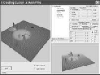
Figure A.3 is a screenshot of running Tutorial A.3. This tutorial is similar to
Tutorial A.2 except that in this case, the rectangular floor is implemented by the
UWBD3D
_
PrimitiveMeshCustom
mesh.
1
The
PrimitiveMeshCustom
is a simple
n
vertex positions centered around the origin on the
xz
plane. Click on the “Mesh Control” checkbox to bring up the interactive mesh
control window. In the interactive mesh control window, click on the “Control
Grid” checkbox to see the uniformly distributed control vertices (CV). The top
two slider bars let the user select a current CV. Notice that the current CV is
drawn as a red box in the application window. The bottom three slider bars let the
user manipulate the position of the current CV.
2
×
2 mesh with uniform
n
×
Figure A.3.
Tutorial
A.3.
Further Reading
We expect graphics hardware and APIs to eliminate the support for a default il-
lumination model in the near future. Readers are encouraged to refer to Peter
Shirley's
Fundamentals of Computer Graphics
for a more detailed treatment of
this subject.
1
Defined in the
D3D
_
Primitive
subfolder of the
D3D Files
folder of the
UWBGL
_
D3D
_
Lib18
project.


Search WWH ::

Custom Search