Graphics Reference
In-Depth Information
14.5
The Eye Transform: WC to EC
This is the second stage of the transformation pipeline where vertices are trans-
formed from WC to EC. To understand this stage, we must first understand what
the EC space is.
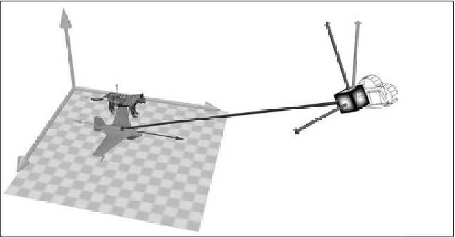
Figure 14.15.
The im-
age generated by the cam-
era from Figure 14.16.
14.5.1
The Eye Coordinate (EC) Orthonormal Basis
In 3D space, an orthonormal basis is defined to be three perpendicular unit vectors
(see the discussion in Section B.4). In this case, we are interested in deriving three
perpendicular unit vectors anchored at the eye position.
As illustrated on the left of Figure 14.16, a camera is specified based on three
parameters: camera (or eye) position
p
e
(
,
and the up vector (
V
up
). We have defined the view vector (
V
v
) to point in the
direction from the eye position toward the look-at position, or
x
e
,
y
e
,
z
e
)
, look-at position
p
a
(
x
a
,
y
a
,
z
a
)
V
v
=
p
a
−
p
e
.
If we cross the view vector (
V
v
) with the up vector (
V
up
),
The sign of the cross prod-
uct.
Remember that
V
w
=
V
up
×
V
v
,
V
1
×
V
2
=
−
(
V
2
×
V
1
)
.
Notice the definition for
V
w
and
V
u
. To maintain right-
handed coordinate directions,
the order of the cross-product
operation is important.
then the vector
V
w
is perpendicular to both the view vector and the up vector.
Remember that the user-specified up vector,
V
up
, is usually not perpendicular to
V
up
= (0, 1, 0)
V
u
= V
v
x V
w
V
v
= p
a
- p
e
V
w
= V
up
x V
v
Look At
Position (
p
a
)
Camera or Eye
Position (
p
e
)
Figure 14.16.
The orthonormal basis of eye (camera) space.


Search WWH ::

Custom Search