Graphics Reference
In-Depth Information
unique positions. With a depth range of 18, the hardware will be able to resolve
distances of
18
65536
≈
δ
=
.
.
0
000275 units
In this case, the hardware will not be able to resolve depth distances of less than
δ
.
That is, if objects are
x
distances away from the camera, the hardware will
not
be able to determine which is in the front. If we did not optimize the near/far
plane settings and set the near plane to 0
±
δ
1 and far plane to 10
6
, we would have
the benefit of not having to worry about squares being clipped away by the near/far
planes. However, it would also mean that the hardware must represent a 10
6
range
basedon16bits,or,
.
10
6
65536
≈
δ
=
15
.
259 units
.
In this case, the hardware will not be able to determine front/back ordering if
objects are less than 15
.
259 units apart!
Tutorial 14.4.
Project Name:
D3D
_
AdjustDepth
Library Support:
UWB_MFC_Lib1
Tutorial 14.4. Near/Far Plane Depth Range
•
Goal.
Understand the importance of near/far plane settings.
•
Approach.
Interactively manipulate near/far plane settings to observe the
effects of hardware unable to resolve depth range.
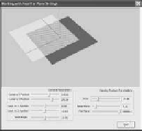
Figure 14.14 is a screenshot of running Tutorial 14.4. In this case, we have ad-
justed the GUI slider bars such that the application window shows two squares
where one square seems transparent, with an interesting pattern in the overlap-
ping area. What we are seeing here is actually an error due to hardware precision.
In this tutorial, we change the two squares slightly such that
Figure 14.14.
Tutorial
14.4.
⎧
⎨
V
a
=
−
4
.
0
,
0
.
001
,
4
.
0
)
,
V
b
=(
4
.
0
,
0
.
001
,
4
.
0
)
,
Grey square:
⎩
=(
.
,
.
, −
.
)
,
V
c
4
0
0
001
4
0
V
d
=
−
4
.
0
,
0
.
001
, −
4
.
0
)
,
and
⎧
⎨
=
−
.
,
.
, −
.
)
,
V
a
2
0
0
0
2
0
V
b
=(
.
,
.
, −
.
)
,
6
0
0
0
2
0
Yellow square:
⎩
V
c
=(
6
.
0
,
0
.
0
,
6
.
0
)
,
V
d
=
−
2
.
0
,
0
.
0
,
6
.
0
)
.


Search WWH ::

Custom Search