Graphics Reference
In-Depth Information
⎧
⎨
V
a
=
−
4
.
0cm
,
0
.
0cm
,
4
.
0cm
)
,
V
e
=
−
9
.
0cm
,
0
.
0cm
,
4
.
0cm
)
,
.
Small paper:
⎩
V
f
=
−
9
.
0cm
,
0
.
0cm
,
9
.
0cm
)
,
V
g
=
−
4
.
0cm
,
0
.
0cm
,
9
.
0cm
)
.
The camera is located at
Camera position
=(
0
.
0cm
,
10
.
0cm
, −
25
.
0cm
)
and points toward the origin (center of the large paper). Once again, notice the
counterclockwise vertex specification, that is,
V
a
→
V
b
→
V
c
→
V
d
.
13.3
A Computer Graphics Simulation
Tutorial 13.1.
Project Name:
Rectangles3D
Library Support:
UWB
_
MFC
_
Lib1
Tutorial 13.1. Drawing the Papers of Figure 13.1
•
Goal.
Demonstrate the essential elements of a 3D program.
•
Approach.
Examine the drawing procedures of a simple program that sim-
ulates the photograph of Figure 13.1.
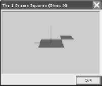
Figure 13.7 is a screenshot of running Tutorial 13.1. The source code of this
tutorial is based on that from Tutorial 3.1 where there was
no
UWBGL
library sup-
port. Recall that Tutorial 3.1 was our first 2D graphics program to draw the two
squares of Figure 3.1. In this tutorial, we modify the source code to show a sim-
ilar scene with two squares in a 3D graphics program. The simplicity of these
two programs allows the clear illustration of the changes involved between sim-
ilar 2D and 3D graphics programs. The source code shown in Listing 13.1 is
identical to that of Listing 3.2 (on p. 81). To refresh our memories, this listing
shows that the drawing area of Tutorial 13.1,
GrfxWindowD3D
, is a subclass of the
MFC CWnd
class. Recall from Figure 3.6 that in the absence of the elaborate
UWBGL
abstractions, we
replace
the drawing area into the application window (label A)
and service the
OnPaint()
event (label B) to draw in this drawing area. The
D3D-specific variables at label C are properly initialized during the construction
of
GrfxWindowD3D
. Listing 13.2 is the
OnPaint()
service routine that renders the
image of Figure 13.7. When compared with the same function from Tutorial 3.1
(Listing 3.3 on p. 82), we notice the identical four-step procedure. Once again,
we verify that independent of the actual application, the principle of working
Figure 13.7.
Rendered
image of the two pieces
of paper from Figure 13.1
with D3D.


Search WWH ::

Custom Search