Graphics Reference
In-Depth Information
uv=(0,0)
uv=(1,0)
Y
xy=(-1,1)
xy=(cosθ, sinθ)
U
cosθ
u= 0.5x + 0.5
sinθ
θ
X
v= 1 - (0.5y + 0.5)
xy=(-1,-1)
xy=(1,-1)
uv=(0,1)
uv=(1,1)
V
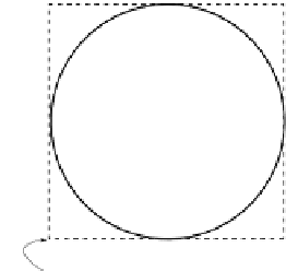
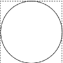
Figure 12.18.
The circle
xy
position and
uv
texture placement.
(
DrawUnitCirce()
). At label A, we see the declaration of four vertices with the
new vertex format (
DeviceVertexFormat
) from Listing 12.8. At label B, each
vertex is assigned with the corresponding geometric
xy
values and the appropriate
uv
texture-placement values according to Figure 12.14. At label C, we first inform
the API about the vertex format with the
SetFVF()
function, and then we draw
the vertices as a triangle-fan. At label D, we compute the geometric
xy
vertex
positions for the unit circle, whereas the
uv
texture placements are computed at
label F. The left side of Figure 12.18 shows the
xy
position of a circle with unit
radius centered around the origin. The right side of Figure 12.18 shows that our
uv
texture placement strategy is to maximize the image in the circle. In this case,
the
xy
coordinate space covered by the circle is
⎧
⎨
center
=(
c
x
,
c
y
)=(
0
,
0
)
,
xy
geometric range
=
=
=
.
,
width
W
x
2
0
⎩
height
=
H
y
=
2
.
0
,
and our texture-placement strategy is to define the same circle to occupy the max-
imum
uv
texture coordinate space, or
Coordinate transformation.
See Figure 10.16 (on p. 273)
and Equation (10.14), where
we learned about transforming
positions
⎧
⎨
=(
,
)=(
.
,
.
)
,
center
c
u
c
v
0
5
0
5
uv
texture coordinate range
=
width
=
W
u
=
1
.
0
,
⎩
between
bounded
height
=
H
v
=
1
.
0
.
coordinate regions.
Notice that we have an almost identical situation to the coordinate transformation
in Chapter 10. The only difference here is the fact that the
y
-axis and
v
-axis
directions are opposite. Similar to the hardware-to-device coordinate transform,
we will have to flip the
y
-axis values. If
v
is defined with respect to the lower-left


Search WWH ::

Custom Search