Graphics Reference
In-Depth Information
- SceneNode
M
b
C
b0
R
b1
Body
Right
Left
M
la
M
ra
R
a0
R
a1
R
a2
R
a0
R
a1
R
a2
Arm
Arm
M
lp
M
rp
C
p0
R
p1
C
p0
R
p1
Palm
Palm
Figure 11.14.
SceneNode
structure for Tutorial 11.6.
components. The scene graph is a more general hierarchy where either scene
nodes or groups of primitives are shared. The sharing of scene nodes or primi-
tives is referred to as instancing. As we will see, instancing allows more efficient
resource utilization; however, the resulting scene graph becomes tricky to control
and maintain. Our source code library does not support instancing.
Tutorial 11.6. Working with a General Scene Tree
Tutorial 11.6.
Project Name:
D3D
_
SceneNodeSiblings
Library Support:
UWB_MFC_Lib1
UWB_D3D_Lib11
•
Goal.
Demonstrate that we can build an arbitrarily complex scene tree
based on the
SceneNode
class.
•
Approach.
Design and work with a scene tree hierarchy with multiple child
branches involving more than one generation of descendants.
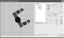
Figure 11.12 is a screenshot of running Tutorial 11.6. In this tutorial, the simple
arm scene hierarchy is replaced with a more complex two-arm human model.
Figure 11.13 shows the details of the model. The base of the model is defined
by the torso (rectangle
R
b
1
) and the head (circle
C
b
0
) with pivot position located
at
P
b
(the origin). We see that the
CArm
hierarchy defines the left and right arms
of the model. In this case, we would like to have control over the entire human
model (e.g., rotating the entire model) while retaining the independent arm and
palm control over the left and right arms.
Figure 11.14 shows an implementation of the human model of Figure 11.13
with five
SceneNode
objects. In this implementation, the two children of the
Base
scene node are both instances of the
CArm
object from Tutorial 11.5. Notice
that each of the scene nodes has its own transformation operator. In this case,
M
b
is the transformation operator of the
Body
node, and
M
la
and
M
lp
are the
operators for the left
Arm
and
Palm
nodes, whereas
M
ra
and
M
rp
are the opera-
tors for the right
Arm
and
Palm
nodes. Listing 11.11 shows the implementation
of Figure 11.14 in the
CModel
class.
Figure 11.12.
Tutorial
11.6.
R
b1
C
b0
P
b
Left
Right
Figure 11.13.
Model for
Tutorial 11.6.
At label A, we see the
m
_
Body
defining


Search WWH ::

Custom Search