Graphics Programs Reference
In-Depth Information
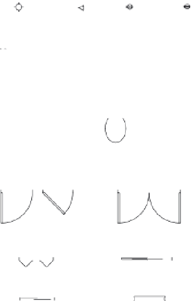
FIGURE 2.12
Samples of stan-
dard symbols used
in architectural
drawings
Incandescent light
Telephone
Outlet
Triplex outlet
Square lav
Pedestal lav
Kitchen sink
Round lav
Bathtub
Toilet
Urinal
Single door
Double door
Pocket door
Bifold door
Sliding door
Window
3.
Pick a point representing the center of the arc near, but not too close to, the upper-left
corner of the door (see the top image in Figure 2.13). The Specify start point of arc:
prompt appears.
4.
Type
@3<0
↵. Metric users should type
@9<0
↵. The Specify end point of arc or
[Angle/chord Length]: prompt appears.
5.
Move the mouse and a temporary arc appears, originating from a point 3 units to the
right of the center point you selected and rotating about that center, as in the middle
image in Figure 2.13. (Metric users will see the temporary arc originating 9 units to the
right of the center point.)
As the prompt indicates, you now have three options. You can enter an angle, a chord
length, or the endpoint of the arc. The prompt default, to specify the endpoint of the
arc, picks the arc's endpoint. Again, the cursor is in Point Selection mode, telling you it's
waiting for point input. To select this default option, you only need to pick a point on the
screen indicating where you want the endpoint.
6.
Move the cursor so that it points in a vertical direction from the center of the arc. You'll
see the Polar Tracking vector snap to a vertical position (Figure 2.14).
7.
Click any location with the Polar Tracking vector in the vertical position. The arc is now
fixed in place, as in the bottom image of Figure 2.13.