Graphics Programs Reference
In-Depth Information
6.
Click the main solid model.
7.
Click the inserted solid.
8.
At the Delete the source object [Yes/No]<N>: prompt, enter
Y
↵↵.
You now have an outline of the intersection between the two solids imprinted on the top sur-
face of your model. The imprint is really a set of edges that have been added to the surface of the
solid. To help the imprint stand out, try the following steps to change its color:
1.
Choose Modify
Solid Editing
Color Faces, or type
SOLIDEDIT
↵
F
↵
L
↵.
2.
Click the imprint from the previous exercise. The imprint and the entire top surface are
highlighted.
3.
At the Select faces or [Undo/Remove/ALL]: prompt, type
R
↵; then click the outer
edge of the top surface to remove it from the selection set.
4.
Press ↵ to open the Color Palette dialog box.
5.
Click the red color sample in the dialog box, and then click OK. The imprint is now red.
6.
Press ↵ twice to exit the command.
7.
To see the full effect of the Color Faces option, choose the Conceptual or Realistic visual
style from the Visual Styles menu in the Viewports Control.
If you want to remove an imprint from a surface, B-click the imprint and press the Delete key.
S
E P A R A T I N G
A
D
I V I D E D
S
O L I D
While editing solids, you can end up with two separate solid forms that were created from one
solid, as shown in Figure 22.32. Even though the two solids appear separated, they act like a
single object. In these situations, AutoCAD offers the Modify
Solid Editing
Separate option.
Choose this option or type
SOLIDEDIT
↵
B
↵
P
↵ and select the solid that has been separated
into two forms.
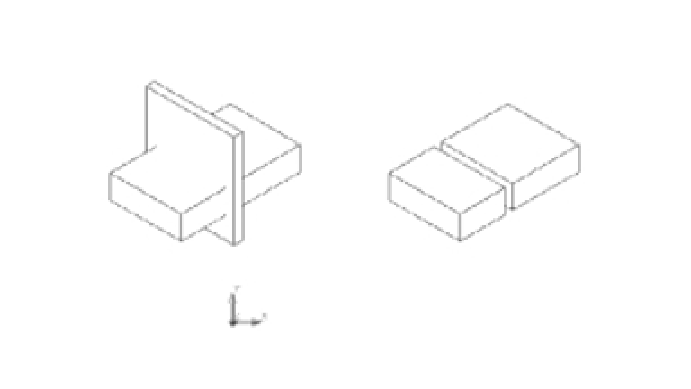
FIGURE 22.32
When the tall, thin
solid is subtracted
from the larger
solid, the result
is two separate
forms, yet they
still behave as a
single object.
The result is two forms
that act like a single object
when selected.
Subtract the tall,
thin solid from the
flat solid.
Separate will separate the two forms
into two distinct solids.