Graphics Programs Reference
In-Depth Information
3.
At the prompt
Select first line or [Undo/Polyline/Distance/Angle/Trim/mEthod/Multiple]:
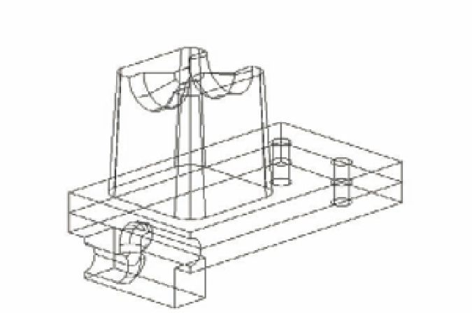
pick the edge of the hole, as shown in Figure 22.20. Notice that the top surface of the
solid is highlighted and that the prompt changes to Enter surface selection option
[Next/OK (current)] <OK>:. The highlighting indicates the base surface, which will be
used as a reference in step 5. (You could also type
N
↵ to choose the other adjoining sur-
face, the inside of the hole, as the base surface.)
FIGURE 22.20
Picking the edge to
chamfer
Select the edge of this hole.
4.
Press ↵ to accept the current highlighted face.
5.
At the Specify base surface chamfer distance or [Expression] <0.1250>:
prompt, type
0.125
↵. This indicates that you want the chamfer to have a width of 0.125
across the highlighted surface.
6.
At the Specify other surface chamfer distance or [Expression] <0.2000>:
prompt, type
0.2
↵.
7.
At the Select an edge or [Loop]: prompt, click the top edges of both holes, and then
press ↵. When the Chamfer command has completed its work, your drawing looks like
Figure 22.21.
8.
After reviewing the work you've done here, save the Bracket.dwg file.
The Loop option in step 7 lets you chamfer the entire circumference of an object. You don't
need to use it here because the edge forms a circle. The Loop option is used when you have a
rectangular or other polygonal edge you want to chamfer.