Graphics Programs Reference
In-Depth Information
2.
Select the seat surface, and press ↵ to fi nish your selection.
3.
At the Specify thickness <0´-0˝>: prompt, enter
0.01
↵, or
0.025
↵ for metric users.
The seat surface appears to lose its webbing, but it has just been converted to a very thin
3D solid.
Shaping the Solid
The butterfl y chair is in a fairly schematic state. The corners of the chair are sharply pointed,
whereas a real butterfl y chair would have rounded corners. In this section, you'll round the cor-
ners of the seat with a little help from the original rectangles you used to form the layout frame.
First, you'll use the Fillet command to round the corners of the rectangles. Then, you'll use
the rounded rectangles to create a solid from which you'll form a new seat:
1.
Choose the Fillet tool from the lower portion of the Tool Sets palette, or enter
F
↵ at the
Command prompt.
2.
Enter
R
↵ for the fi llet radius option.
3.
Enter
3
↵ to set the radius. Metric users enter
7. 5
↵.
4.
Enter
P
↵ for the Polyline option.
5.
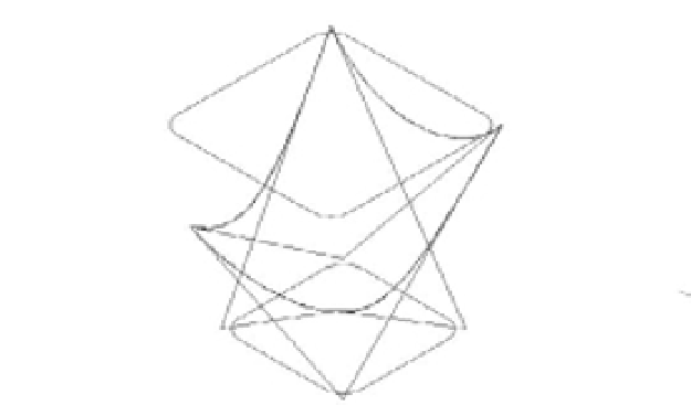
Select the top rectangle, as shown in Figure 20.36. The polyline corners become rounded.
FIGURE 20.36
Round the corners
of the rectangles
with the Fillet
command.
Start the Fillet command,
and select the top
rectangle to round
its corners.
Repeat the Fillet command
to round the corners of
the bottom rectangle.
6.
Press ↵ to repeat the Fillet command.
7.
Enter
P
↵ to use the Polyline option, and then click the bottom rectangle as shown in
Figure 20.36. Now both polylines have rounded corners.
Next, create a 3D solid from the two rectangles using the Loft tool:
1.
Click the Loft tool near the top of the Tool Sets palette, or enter
LOFT
↵.
2.
Select the two rectangles and press ↵ to fi nish your selection.