Graphics Programs Reference
In-Depth Information
In step 4, you selected the corner of the box, but the box didn't appear right away. You had
to enter a Z value in step 5 before the outline of the box appeared. Then, in step 5, you saw the
box begin at the 36˝ elevation. Using point filters allowed you to place the box accurately in the
drawing even though there were no features that you could snap to directly.
Now that you've gotten most of the unit modeled in 3D, you'll want to be able to look at it
from different angles. Next you'll see some of the tools available to control your views in 3D.
Moving around Your Model
AutoCAD offers a number of tools to help you view your 3D model. You've already used one
to get the current 3D view. Choosing SW Isometric from the 3D Views menu on the Viewport
Controls displays an isometric view from a southwest direction. You may have noticed several
other isometric view options in that menu. The following sections introduce you to some of the
ways you can move around in your 3D model.
Finding Isometric and Orthogonal Views
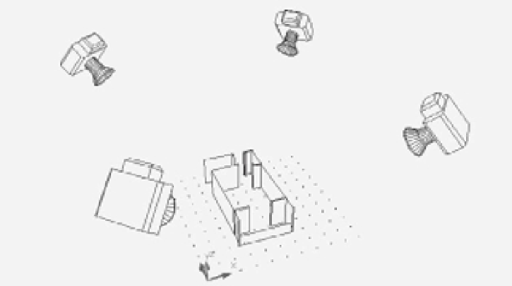
Figure 19.32 illustrates the isometric view options you saw earlier: SE Isometric, SW Isometric,
NE Isometric, and NW Isometric. The cameras represent the different viewpoint locations. You
can get an idea of their location in reference to the grid and UCS icon.
FIGURE 19.32
The isometric
viewpoints for
the four isomet-
ric views avail-
able from the
3D Views menu.
NW Isometric
SW Isometric
NE Isometric
SE Isometric
The 3D Views menu also offers another set of options: Top, Bottom, Left, Right, Front, and
Back. These are orthogonal views that show the sides, top, and bottom of the model, as illus-
trated in Figure 19.33. In this figure, the cameras once again show the points of view.
When you use any of the view options described here, AutoCAD attempts to display the
extents of the drawing. You can then use the Pan and Zoom features to adjust your view.