Graphics Programs Reference
In-Depth Information
FIGURE 19.28
Turn off
Dynamic UCS
Allow/Disallow Dynamic UCS
3.
Click the Box tool near the top of the Tool Sets palette.
4.
Use the Endpoint osnaps, and click the two points shown in Figure 19.27.
5.
At the Specify height or [2Point] <8´-0˝>: prompt, point the cursor downward
from the points you just selected, and enter
12
↵. Metric users should enter
30
↵. The door
header appears.
6.
Repeat steps 4 and 5 to draw the door headers shown in Figure 19.29.
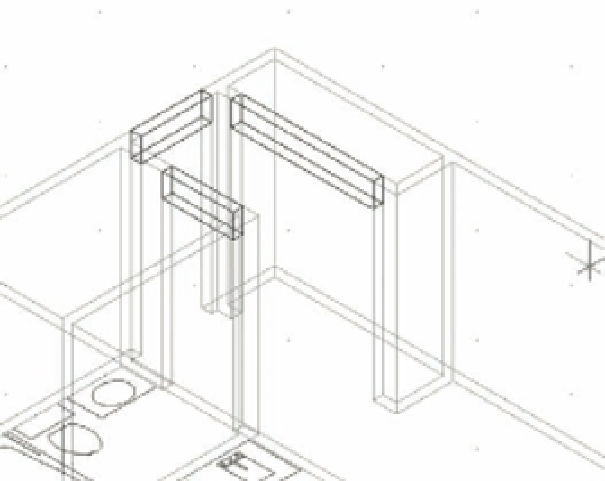
FIGURE 19.29
Adding the
remaining door
headers
Add these three door headers.
The walls and door headers give you a better sense of the space in the unit plan. To enhance
the appearance of the 3D model further, you can join the walls and door headers so they appear
as seamless walls and openings:
1.
Zoom out so you can see the entire unit, and then click the Union tool in the Tool Sets
palette (Figure 19.30). You can also enter
UNI
↵.
2.
At the Select objects: prompt, select all the walls and headers, and then press ↵.
Now the walls and headers appear as one seamless surface without any distracting joint
lines. You can really get a sense of the space of the unit plan. You'll want to explore ways of
viewing the unit in 3D, but before you do that, you need to know about one more 3D modeling
feature:
point fi lters
.