Graphics Programs Reference
In-Depth Information
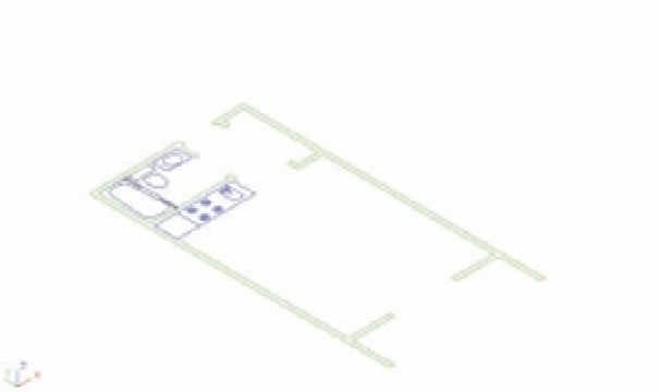
FIGURE 19.24
A 3D view of the
unit plan
Select these polylines
for the Extrude command.
3.
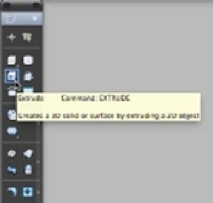
Click the Extrude tool in the Tool Sets palette (Figure 19.25).
FIGURE 19.25
Selecting the
Extrude tool
from the Tool
Sets palette
You can also enter
EXT
↵ at the Command prompt. You see the message Current wire
frame density: ISOLINES=4, Closed profiles creation mode = Solid in the
Command Line palette, followed by the Select objects to extrude or [MOde]:
prompt.
4.
Select the wall outlines shown in Figure 19.24, and then press ↵.
5.
At the Specify height of extrusion or [Direction/Path/Taper angle/
Expression] <-0´-3˝>: prompt, place the cursor near the top of the drawing area and
enter
8´
↵. Metric users should enter
224
↵. The walls extrude to the height you entered, as
shown in Figure 19.26.
Unlike in the earlier exercise with the box, you can see through the walls because this is a
2D wireframe view. A
wireframe view
shows the volume of a 3D object by displaying the lines
representing the edges of surfaces. Later in this chapter, we'll discuss how to make an object's
surfaces appear opaque as they do on the box earlier in this chapter.