Graphics Programs Reference
In-Depth Information
2.
Return to the Edit Vertex option, and place the X at the beginning vertex of a polyline
segment you want to change.
3.
Type
W
↵ to issue the Width option.
4.
At the Specify starting width for next segment <0.0000>: prompt, enter a
value—
12
↵, for example—indicating the polyline width desired at this vertex.
5.
At the Specify ending width for next segment <12.0000>: prompt, enter the
width—
24
↵, for example—for the next vertex.
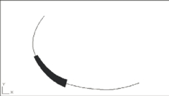
The width of the polyline changes to your specifications (Figure 17.16).
FIGURE 17.16
A polyline with the
width of one seg-
ment increased
1´ width
2´ width
The Width option is useful when you want to create an irregular or curved area in your draw-
ing that is to be filled in solid. This is another option that is sensitive to the polyline direction.
As you've seen throughout these exercises, you can use the Undo option to reverse the last Edit
Vertex option used. You can also use the Exit option to leave Edit Vertex at any time. Enter
X
↵ to
display the Pedit prompt:
Enter an option
[Close/Join/Width/Edit vertex/Fit/Spline/Decurve/Ltype gen/Reverse/Undo]:
FILLING IN SOLID AREAS
You've learned how to create a solid area by increasing the width of a polyline segment. But suppose
you want to create a solid shape or a thick line. AutoCAD prov ides the Solid, Trace, and Donut com-
mands to help you draw simple filled areas. The Trace command acts just like the Line command
(with the added feature of allowing you to draw wide line segments). Solid lets you create solid filled
areas with straight sides, and Donut draws circles with a solid width.
You can create free-form, solid-filled areas by using the Solid hatch pattern. Create an enclosed
area by using any set of objects, and then use the Hatch tool to apply a solid hatch pattern to the
area. See Chapter 7, “Mastering Viewing Tools, Hatches, and External References,” for details on
using the Hatch tool.